Power-cell packaging material

a power-cell and packaging technology, applied in the field of battery packaging materials, can solve the problems of limited weight reduction, difficulty in keeping up with the diversified forms of batteries used in metal packaging materials that are generally used heretofore, etc., and achieve the effect of improving the insulation quality of batteries and high insulation quality

Active Publication Date: 2019-03-19
DAI NIPPON PRINTING CO LTD
View PDF27 Cites 2 Cited by
  • Summary
  • Abstract
  • Description
  • Claims
  • Application Information

AI Technical Summary

Benefits of technology

[0022]According to the battery packaging material of the present invention, it is possible to provide a battery packaging material having high insulation quality even when very small contaminants such as debris of an electrode active material and an electrode tab exist in the part that is to be heat-sealed, such as in an interface between the sealant layers, or between the electrode tab and the sealant layer. That is, by sealing a battery element with the battery packaging material of the present invention, it is possible to improve the insulation quality of the battery.

Problems solved by technology

However, metal packaging materials that are generally used heretofore have difficulty in keeping up with the diversified forms of batteries.
Also weight reduction is limited because the packaging materials are made of metal.

Method used


Image

  • Power-cell packaging material
  • Power-cell packaging material
  • Power-cell packaging material

Examples


exemplary embodiment b

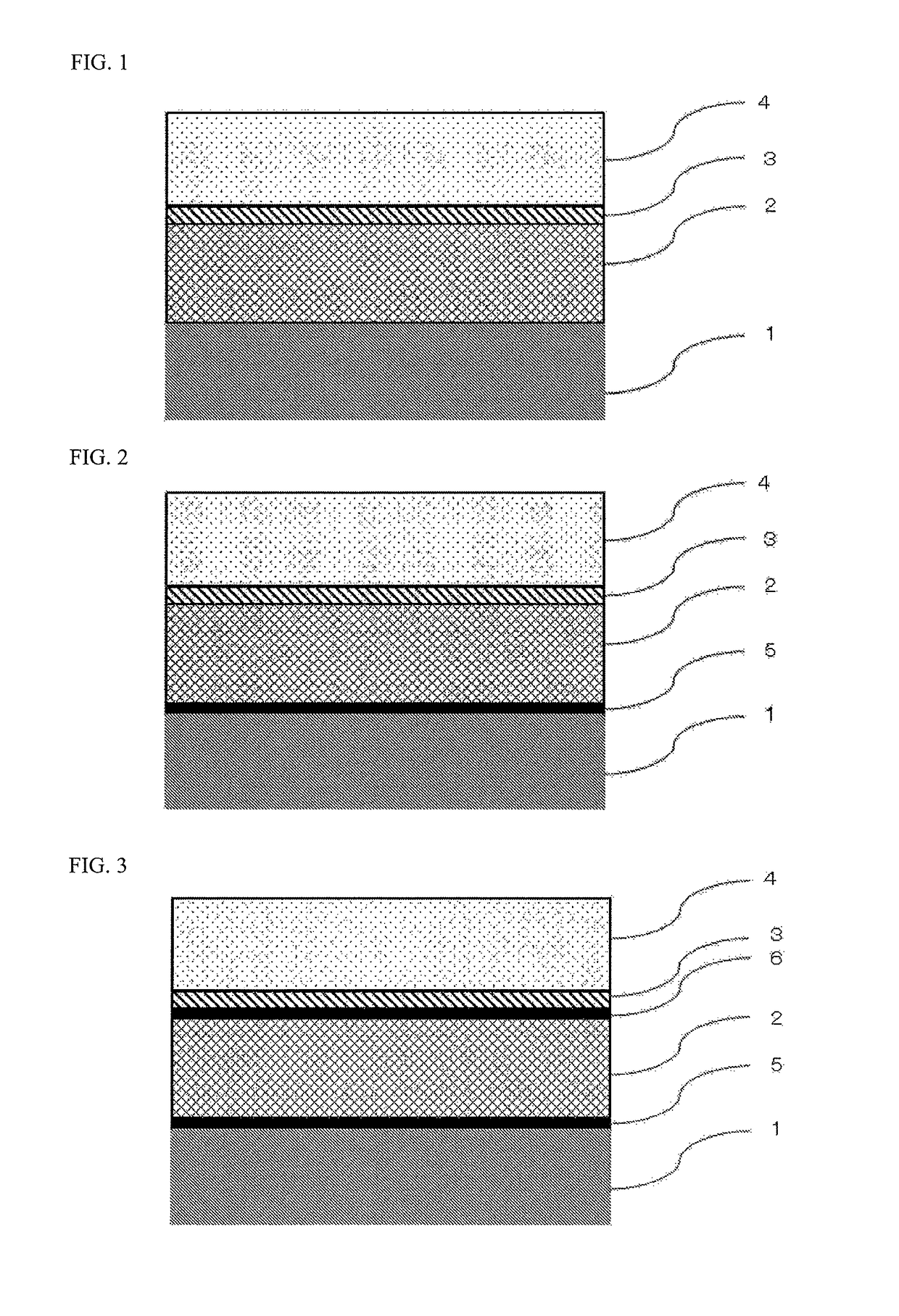
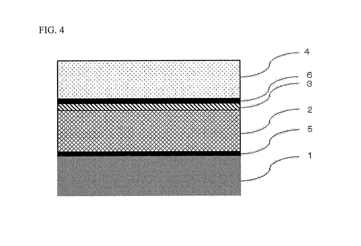
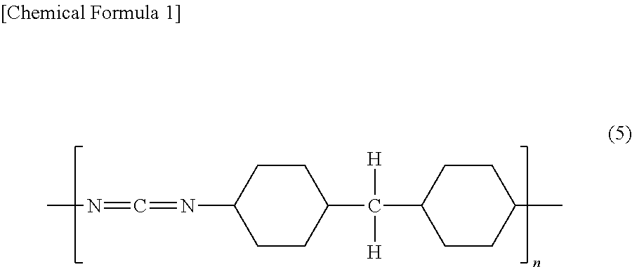
[0082]Preferred exemplary embodiment B of the insulating layer 3 is characterized in that the insulating layer 3 is formed of a resin composition containing a modified polyolefin resin modified with an unsaturated carboxylic acid or acid anhydride thereof, and the carbodiimide compound. The modified polyolefin-based resin may further be modified with a (meth)acrylic acid ester. In Exemplary embodiment B, by forming the insulating layer 3 of a resin composition containing such a modified polyolefin-based resin and the carbodiimide compound, it is possible to improve the insulation quality and the durability of the battery packaging material. As the modified polyolefin resin, two modified polyolefin resins: a modified polyolefin resin modified with an unsaturated carboxylic acid or acid anhydride thereof, and additionally a modified polyolefin resin modified further with a (meth)acrylic acid ester may be used in mixture. The modified polyolefin resin modified further with a (meth)acry...

exemplary embodiment c

[0086]Preferred exemplary embodiment C of the insulating layer 3 is characterized in that the insulating layer 3 is formed of a resin composition containing (i) at least one of a noncrystalline modified polyolefin resin (A) and a modified polyolefin resin (B) having a melting point of greater than or equal to 110° C., and (ii) a modified polyolefin resin (C) having a melting point of less than or equal to 100° C. In Exemplary embodiment C, the insulating layer 3 formed of such a specific resin composition is provided between the metal layer 2 and the sealant layer 4, and thus even when very small contaminants such as debris of an electrode active material and an electrode tab exist between the battery element and the sealant layer, the insulation quality and the durability of the battery packaging material are improved. In other words, in Exemplary embodiment C, as a result of forming the insulating layer 3 of one of the following resin compositions (1) to (3), the effect of improvi...

examples

[0147]Hereinafter, the present invention will be described in detail below by showing Examples and Comparative Examples. It is to be noted that the present invention is not limited to Examples.


PUM

PropertyMeasurementUnit
elastic modulusaaaaaaaaaa
melting pointaaaaaaaaaa

Abstract

A power-cell packaging material including a layered body obtained by layering at least a substrate layer, a metal layer, an insulating layer, and a sealant layer, in this order. The insulating layer has a hardness in the range of 10-300 MPa, when measured by using a nanoindenter and pressing the indenter 5 μm into the insulating layer from a cross-section of the layered body in the layering direction thereof.

Description

TECHNICAL FIELD[0001]The present invention relates to a battery packaging material having high insulation quality.BACKGROUND ART[0002]Conventionally, various types of batteries have been developed. In these batteries, a battery element consisting of electrodes, an electrolyte and so on needs to be sealed in a packaging material or the like. As such a battery packaging material, metal packaging materials are generally used.[0003]In association with the recent advanced performance of electric cars, hybrid electric cars, personal computers, cameras, mobile phones and so on, batteries having a variety of forms are demanded. It is also requested for batteries to have smaller thickness and lighter weight. However, metal packaging materials that are generally used heretofore have difficulty in keeping up with the diversified forms of batteries. Also weight reduction is limited because the packaging materials are made of metal.[0004]Thus, there has been proposed a film-shaped laminate with ...

Claims


Application Information

Patent Timeline
Patent Type & Authority Patents(United States)
IPC IPC(8): H01M2/02B32B7/02B32B15/08B32B27/30B32B27/28B32B37/18B32B37/06B32B15/085B32B27/32B32B27/08B32B15/20B32B7/027H01M50/119H01M50/121H01M50/129H01M50/134H01M50/141
CPCH01M2/029B32B15/08B32B15/085B32B15/20B32B27/08B32B27/28B32B27/308B32B27/32B32B37/06B32B37/182H01M2/0275H01M2/0277H01M2/0285H01M2/0287B32B7/02H01M2002/0297B32B2307/51B32B2307/536B32B2307/7265B32B2311/24B32B2323/04B32B2323/10B32B2439/00B32B2457/10B32B2553/00Y02E60/10H01M50/131H01M50/124Y02P70/50B32B7/027H01M50/141H01M50/121H01M50/129H01M50/119H01M50/134
Inventor OJIRI, TETSUYASUZUKI, TSUYOSHIYOKOTA, KAZUHIKOYAMASHITA, RIKIYAKANDORI, MASAKAZU
Owner DAI NIPPON PRINTING CO LTD
Why Eureka
Try Eureka