Automatic drug delivery devices

a drug delivery device and automatic technology, applied in the direction of ampoule syringes, intravenous devices, needles, etc., can solve the problems of large number of layers of components required and difficult manufacturing, and achieve the effect of reducing device size and noise during operation

Active Publication Date: 2019-03-26
OVAL MEDICAL TECH
View PDF23 Cites 0 Cited by
  • Summary
  • Abstract
  • Description
  • Claims
  • Application Information

AI Technical Summary

Benefits of technology

[0016]The device may be configured such that the first release mechanism is operable only when a front end of the device, through which the drug is delivered, is pressed against an injection site. For autoinjectors, this is a good way to trigger drug delivery as it is simple, requires only one-handed operation and reduces the possibility of accidental operation. The device may further comprise a main housing, which may be part of or separate to the drug container assembly, and a skin contact element, the skin contact element forming a front end of the device (after uncapping), movement of the skin contact element relative to the main housing from an initial position to an insertion position operating or allowing the operation of the first release mechanism.
[0079]In a further aspect of the invention, there is provided a release mechanism for a stored energy source or other source of motive force, comprising: a live hinge, wherein the live hinge is in a folded state to retain the stored energy source and is allowed to expand to release the stored energy source. The live hinge effectively acts as a gearing mechanism to reduce the force required to retain the stored energy source. The release mechanism may be provided in a drug delivery device. Use of a live hinge in this manner provides an effective and low cost means to retain a high force.

Problems solved by technology

Where two springs are provided, complicated interlock mechanisms are required to ensure the correct sequence of operation and the number of layers of components required can become large and difficult to manufacture.

Method used


Image

  • Automatic drug delivery devices
  • Automatic drug delivery devices
  • Automatic drug delivery devices

Examples


first embodiment

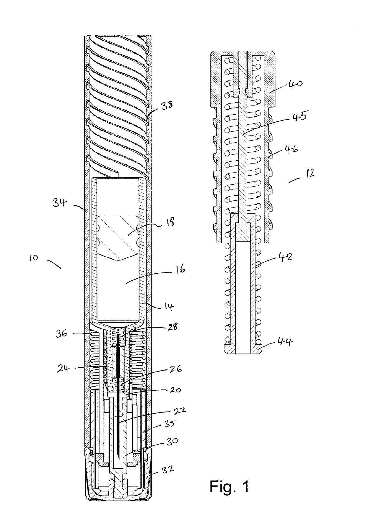
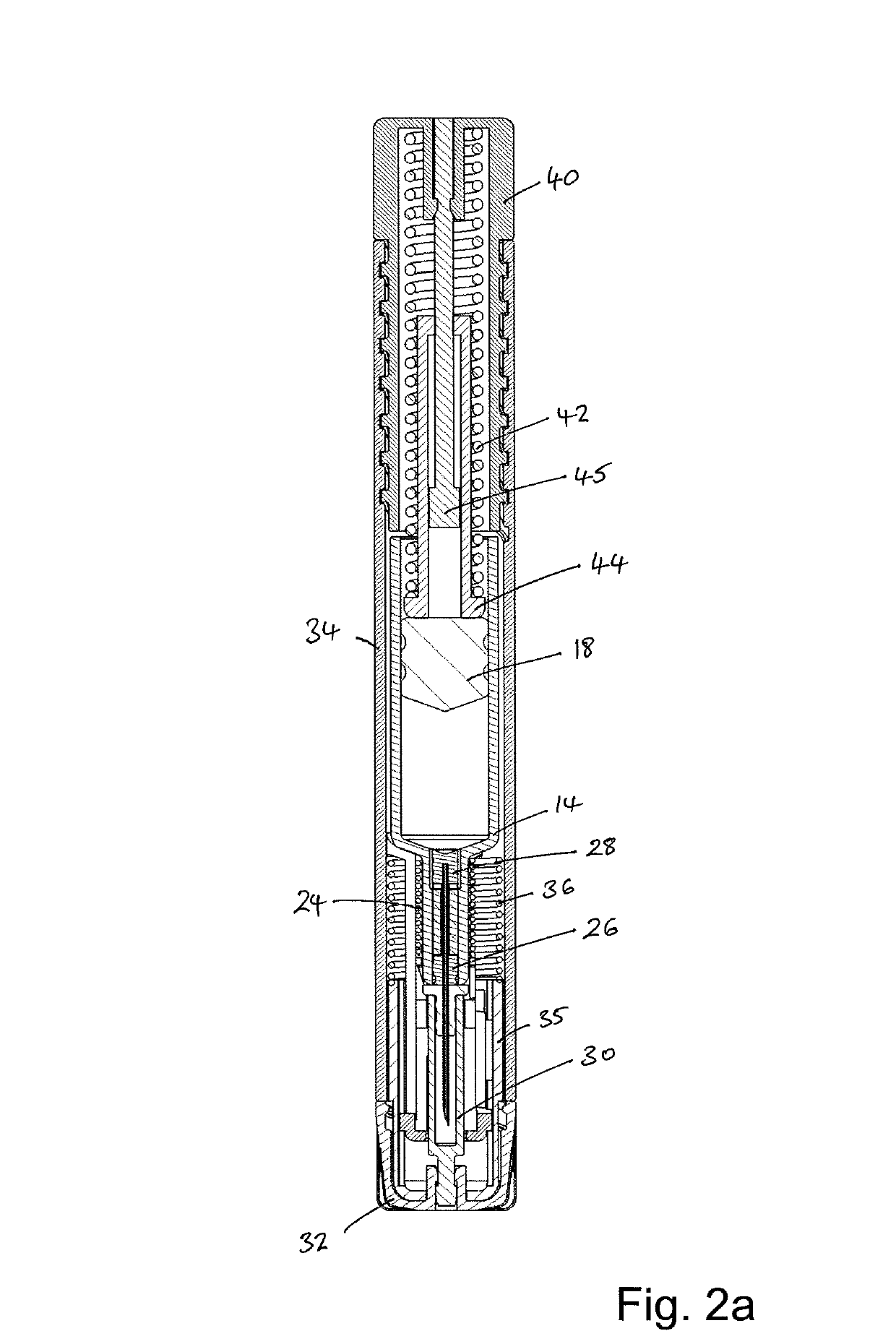
[0129]FIG. 1 is a schematic cross-sectional illustration of a drug delivery device in accordance with the invention. The device comprises a first sub-assembly 10 having a drug container 14 and a needle insertion mechanism, and a second sub-assembly 12 comprising a reusable power pack. The first sub-assembly comprises a drug container 14 containing a drug 16, a plunger 18 within the drug container, a needle hub 20 securely holding a needle 22, and a needle insertion spring 24 positioned between the drug container and the needle hub. The drug container has an outlet that is sealed by a first sealing member 26, and through which the needle 22 passes. The first sealing member 26 is securely retained to the drug container by lobes on the drug container received in corresponding indents in the first sealing member. The distal end of the needle is sealed by a second sealing member 28. The drug 16 is able to pass the second sealing member 28 to flood the space between the first and second s...

second embodiment

[0140]FIG. 11 is a cross-section of the invention, before use. In the embodiment of FIG. 11, the device includes a needle insertion mechanism that is driven by the pressure of the drug within the drug container.

[0141]The device 100 of FIG. 11 comprises a drug container assembly comprising a drug container 114 containing a drug 116 in liquid form or in solution and a plunger 118 provided within the drug container. An outlet of the drug container is sealed by a sealing member 126 and a needle hub 120. The sealing member is an annular, elastomeric sealing member that is compressed between the needle hub 120 and the drug container 114.

[0142]The needle hub 120 holds a hypodermic needle 122. A distal or rear end of the needle is positioned within a cavity 123 in the needle hub to allow drug to enter the needle, as explained below. A proximal or front end of the needle 122, in use, enters an injection site. A needle shield 130 is provided to cover the front end of the needle and keep it st...

third embodiment

[0154]FIG. 22 is a perspective view of a third embodiment, comprising a drug delivery device within an exterior package. The package 200 is a clamshell type package. FIG. 23a shows the package of FIG. 22 in a open position, revealing the drug delivery device. It can be seen that the package 200 includes an interior finger 201, which, when the package is closed, is received in an opening 211 in the device 210.

[0155]FIG. 23b is a view of the device of FIG. 23a, with the package and the housing of the device removed for clarity. The device comprises two separate drug containers, each of which provides drug to the same hypodermic needle. Each drug container has an associated drive mechanism. The drugs within each drug container may be the same or different to each other.

[0156]The drive mechanism comprises two compression springs 244 positioned between a rear housing 240 of the device and a central beam of a pusher element 242. When the package is closed, the finger 201 engages a front f...


PUM


Abstract

The invention provides in one aspect a drug delivery device comprising a drug container (16), and a plunger (18) positioned within the container assembly, the drug container assembly having an outlet for dispensing the drug, wherein, in an initial position, the outlet is sealed; a drive mechanism comprising a first stored energy source (42) operable to apply pressure on the plunger or the drug container to pressurize the drug, and a first release mechanism operable to unseal the outlet after the drug has been pressurized. In another aspect, there is provided a drug delivery device comprising a housing, including an external housing portion configured to be held in use and a drug containing portion containing a drug, a needle assembly comprising a needle fixed to a needle hub, the needle hub configured to move relative to the drug containing portion from an initial position within the housing to an insertion position in which the needle extends beyond the housing, a first stored energy source configured to move the needle hub from the initial position to the insertion position, and a plunger within the housing and configured to move relative to the drug containing portion to eject the drug through the needle when the needle is in the insertion position.

Description

CROSS-REFERENCE TO RELATED APPLICATIONS[0001]This application is a U.S. National Stage Application under 35 U.S.C. § 371 of International Application No. PCT / EP2013 / 071805, filed Oct. 17, 2013, which is hereby incorporated herein by reference in its entirety. PCT / EP2013 / 071805 claims priority to Great Britain Patent Application No. 1218667.2 filed Oct. 17, 2012, and to Great Britain Patent Application No. 1303577.9 filed Feb. 28, 2013.FIELD OF THE INVENTION[0002]The present invention relates to automatic injectors, often referred to as autoinjectors that can provide both automatic needle insertion and automatic ejection of the drug through the needle.BACKGROUND TO THE INVENTION[0003]One type of drug delivery device known in the art is an autoinjector, which contains a medical, therapeutic, diagnostic, pharmaceutical or cosmetic compound (drug) before it is administered, and which is used to administer the compound through the skin of the patient via a hollow needle. Autoinjectors ma...

Claims


Application Information

Patent Timeline
Patent Type & Authority Patents(United States)
IPC IPC(8): A61M5/20A61M5/32A61M5/00A61M5/19A61M5/24
CPCA61M5/2033A61M5/3287A61M5/002A61M5/19A61M2005/202A61M2005/2488A61M2005/208A61M2005/2013A61M2005/2073A61M2005/2462A61M2005/2474A61M2005/206
Inventor YOUNG, MATTHEWLAMBLE, RALPH
Owner OVAL MEDICAL TECH
Why Eureka
Try Eureka