Personal flight vehicle

Active Publication Date: 2019-03-26
OMNI HOVERBOARDS INC
View PDF57 Cites 7 Cited by
  • Summary
  • Abstract
  • Description
  • Claims
  • Application Information

AI Technical Summary

Benefits of technology

[0075]In some implementations, the propulsion systems are arranged and operated to minimize the gyroscopic effects that affect the vehicle, and to minimize gyroscopic-induced stresses within the platform base assembly.
[0261]a.4 the frame is approximately symmetrical about the YZ plane. The frame may also be approximately symmetrical about the XZ plane.b. Propulsion means providing thrust in mid-air. The propulsion means can be divided in two sets of propulsion systems that are approximately symmetrical about the YZ axis. High-speed rotating parts create a gyroscopic effect, and, if not minimized, can make the vehicle difficult to control. In order to minimize global gyroscopic effects (the gyroscopic effect generated by the machine as a whole), the high inertial momentum and high-speed rotating parts of the first set rotate in the opposite direction from their corresponding symmetrical part in the second set. However, the gyroscopic effect of each propulsion system can also be minimized, or, if possible, cancelled, as it generates stress inside the vehicle's body during quick changes in direction, and may also generate a twisting movement in some situations. Minimization of the gyroscopic effects of the propulsion system can be achieved through an optimal usage of materials and mass distribution, but can also be achieved with high-speed counter-rotating flywheel(s), or counter-rotating propellers or fans.

Problems solved by technology

In-flight payload droppings or construction of miniaturized aerial vehicles may cause problems, e.g. because sensors cannot be mounted perfectly in the CG or because the CG is shifted out of the origin of the initially assumed body fixed coordinate system.

Method used


Image

  • Personal flight vehicle
  • Personal flight vehicle
  • Personal flight vehicle

Examples


example 1

r Implementation of the Vehicle

[0413]FIG. 5 presents an electric octo-copter implementation of the invention. The vehicle is built according to the general description of the invention and to the detailed description of the preferred embodiments, considering that an un-ducted electrical propeller based solution is adopted. In this case, the vehicle consists of:

A Carbon-Fiber Frame

[0414]The frame has a shape described in FIG. 19 and wherein:[0415](190), the length of the small motor arms is in the range of 0.5 m to 0.75 m;[0416](191), the length of the long motor arms is in the range of 0.6 m to 0.9 m;[0417](192), the length of the flexible link between attachment areas 15 and 16 is in the range of 0.5 m to 0.75 m, with a torsion elastic modulus ranging from 100 Nm / rad to 1000 Nm / rad;[0418](194), the angle between the 2 long motor arms ranges from 45 to 60 degrees;[0419](193), the angle between the one long motor arm and a short one is in the range of 55 to 70 degrees;[0420]the heigh...

example 2

ed-Fan Implementation of the Vehicle

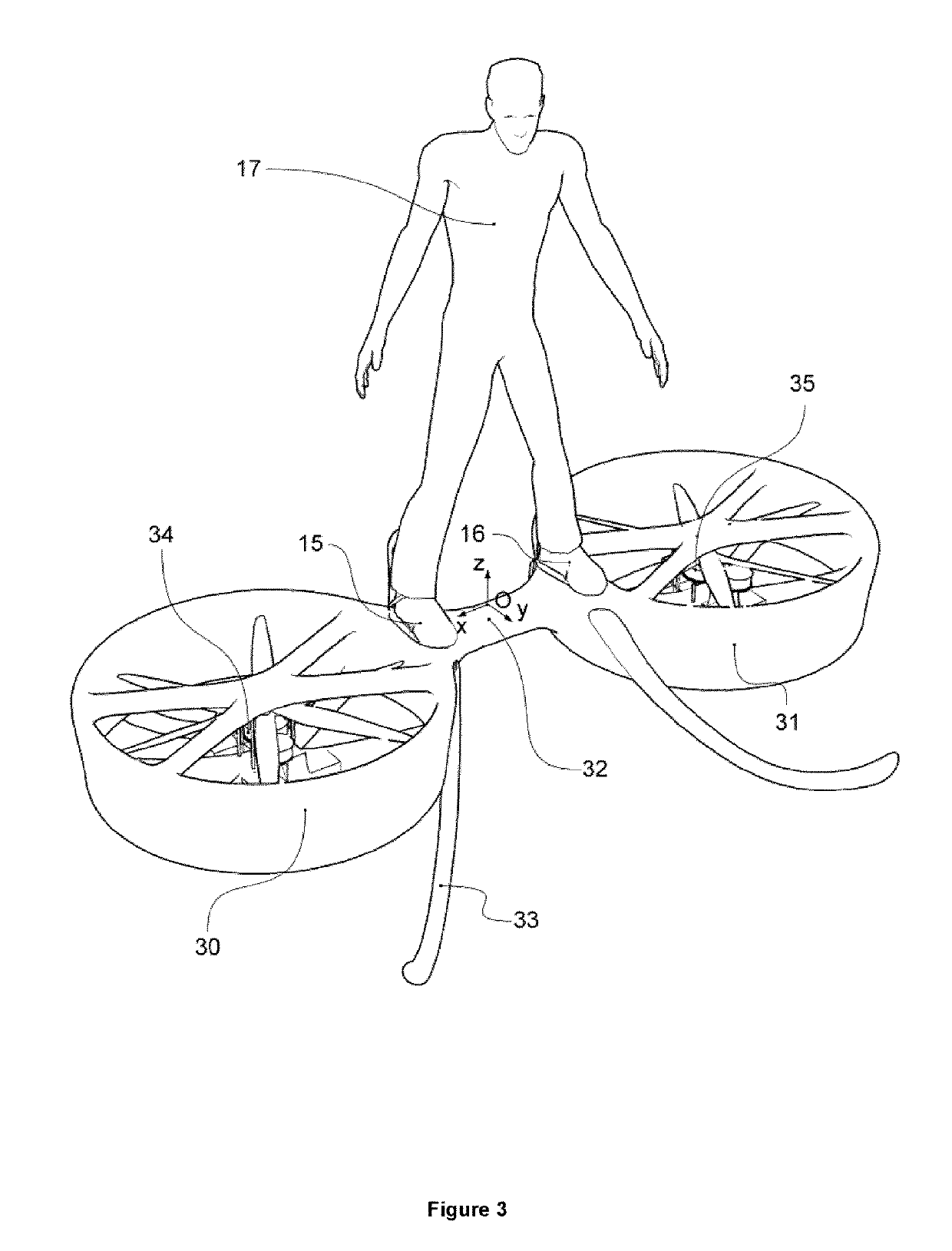
[0429]FIG. 3, FIG. 20 and FIG. 21 present a dual ducted-fan implementation of the invention. The vehicle is to be built according to the general description of the invention and to the detailed description of the preferred embodiments, considering that two ducted fans are used as the propulsion means. Moreover, each ducted fan has 2 sets of counter-rotating propellers, each set of propellers being powered by its dedicated motor; the motors are reciprocal combustion engines. In this case, the aircraft consists of a carbon fiber frame (30,31,32).

[0430]The frame has a shape described in FIG. 3 and also in FIG. 20 or 21 wherein:[0431]the duct internal diameter (201) is in the range of 0.6 to 1.2 m;[0432]the length of the flexible link (200) between attachment areas 15 and 16, ranges from 0.5 m to 0.75 m;[0433]the height of the vehicle is in the range of 0.4 m to 0.8 m; and[0434]the landing arms have a projected length onto the platform based assembly'...

example 3

pe Implementation of the Vehicle

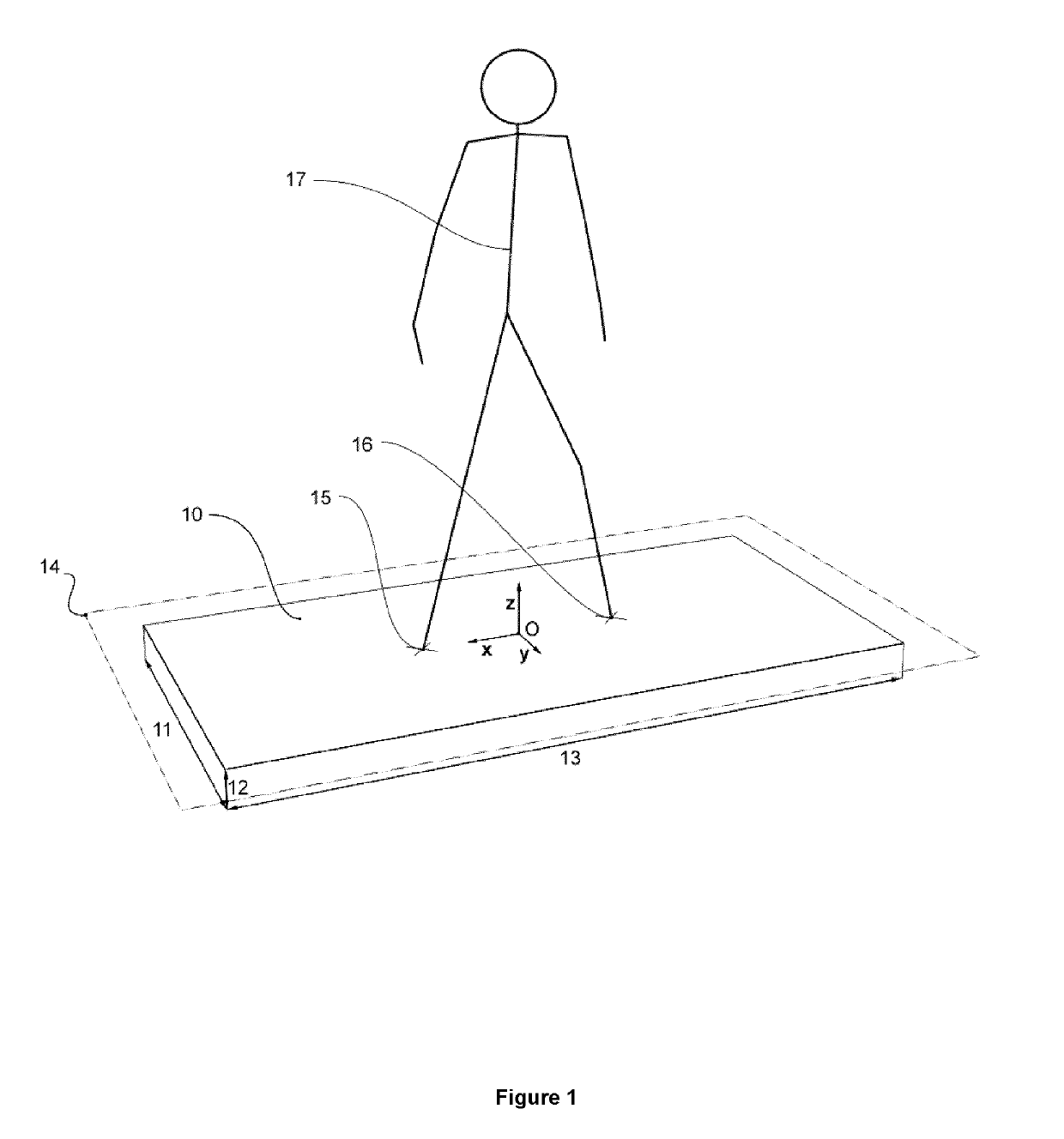
[0441]FIGS. 22, 23 and 24 present an implementation of the invention using a total of 6 ducted fans. The shape of the vehicle in this implementation resembles a board, more specifically, it is a rounded-rectangular shape vehicle, where its shape about the X-Y axis is a rounded rectangle with an aspect ratio of about 2.5 to 1, longer towards the X axis, and where the dimension of the board about the Z axis is significantly lower than about the X or Y axis, in this case, ½th of the dimension about the Y axis.

[0442]The propulsion systems are arranged as follows:[0443]a)—Two main high power ducted fans (220 and 221);[0444]b)—Four control ducted fans (222, 223, 224, and 225);

[0445]The 3D coordinates as well as 3D pointing direction of each ducted fan are described in the Table (12)

[0446]This embodiment is intended for low altitude (0-3 m) flight in hover mode, with limited height and limited maximum velocity. It does not contain any location where the feet...


PUM


Abstract

A personal flight vehicle including a platform base assembly that provides a surface upon which the feet of an otherwise free-standing person are positionable, and including a plurality of axial flow propulsion systems positioned about a periphery of the platform base assembly. The propulsion systems generate a thrust flow in a direction substantially perpendicular to the surface of the platform base assembly, where the thrust flow is unobstructed by the platform base assembly. The thrust flow has a sufficient intensity to provide vertical takeoff and landing, flight, hovering and locomotion maneuvers. The vehicle allows the pilot to control the spatial orientation of the platform base assembly by the movement, preferably direct, of at least part of his or her body, and the spatial movement of the vehicle is thus controlled.

Description

FIELD OF THE INVENTION[0001]The present invention pertains to ultra-light aircrafts, particularly ultra-light aircrafts with Vertical Takeoff and Landing (VTOL), as well as to those with hovering capacity. More particularly, the present invention relates to a personal flight vehicle. In addition, it also refers to the manufacturing processes for building ultra-light aircrafts of the invention, and to various corresponding uses and the learning methods for said uses.BACKGROUND OF THE INVENTION[0002]Various ultra-light aircrafts with vertical takeoff and landing, such as helicopters, are widely recognized as methods for human transportation. Typically, such vehicles have their propulsion systems located over the centers of mass of both the pilot and that of the aircraft, providing stability and enabling a simple landing. These aircrafts are typically controlled through handles, pedals or joysticks. Other types of VTOL vehicles have multiple rotors within a solid frame, and the various...

Claims


Application Information

Patent Timeline
Patent Type & Authority Patents(United States)
IPC IPC(8): B64C27/20B64C39/02B64D31/04B64C15/12B64D27/04B64D27/24B64D27/02
CPCB64C39/026B64C15/12B64C27/20B64D27/24B64D31/04B64D27/04B64D2027/026
Inventor DURU, CATALIN ALEXANDRU
Owner OMNI HOVERBOARDS INC
Why Eureka
Try Eureka