Navigation signal processing device, navigation signal processing method, and navigation signal processing program

a technology of navigation signal and processing method, applied in the field of positioning technique, can solve the problems of inadequacies of the technique disclosed in japanese unexamined patent application laid-open no. 2013 and the tendency to perform positioning using a gnss with less precision, and achieve the effect of preventing the decrease of positioning precision

Active Publication Date: 2019-04-02
KK TOPCON
View PDF7 Cites 2 Cited by
  • Summary
  • Abstract
  • Description
  • Claims
  • Application Information

AI Technical Summary

Benefits of technology

[0006]In view of these circumstances, an object of the present invention is to provide a technique for preventing decrease in the positioning precision due to reflected waves from a navigation satellite that is blocked by an obstacle in a positioning technique using a GNSS.
[0007]A first aspect of the present invention provides a navigation signal processing device including a positioning unit that is configured to perform positioning based on navigation signals from navigation satellites, a setting unit that is configured to set a condition for restricting utilization of the navigation signals from a specific navigation satellite, and a three-dimensional point cloud position data obtaining unit that is configured to obtain three-dimensional point cloud position data of the surroundings of an antenna that receives the navigation signals. In this case, the setting unit sets the condition based on the three-dimensional point cloud position data. According to the first aspect of the present invention, utilization of the navigation satellite is restricted based on the three-dimensional point cloud position data of the surroundings. According to the present invention, decrease in the positioning precision due to the effects of the navigation satellite that is blocked by a building or the like is prevented.
[0008]According to a second aspect of the present invention, in the invention according to the first aspect of the present invention, the setting unit may project a point cloud, which constitutes the three-dimensional point cloud position data, on the celestial sphere surface as viewed from the antenna and may set a condition for restricting utilization of a navigation satellite that is positioned in an area of the celestial sphere surface, at which the point cloud is projected. According to the second aspect of the present invention, utilization of the navigation satellite that is blocked by an object (building, tree, etc.), which is represented by the point cloud, is restricted, whereby decrease in the positioning precision due to multiple paths and the like of the navigation signal is prevented.
[0012]According to the fourth aspect of the present invention, since the processing for restricting the utilization of the navigation signals is performed according to the update of the three-dimensional point cloud position data, the condition for restricting the utilization of the navigation signals is updated constantly according to the three-dimensional condition of the surroundings. Therefore, decrease in the positioning precision is prevented in the case of performing the positioning while the vehicle travels.
[0015]According to the present invention, a technique for preventing decrease in the positioning precision due to reflected waves from a navigation satellite that is blocked by an obstacle is obtained in the positioning technique using a GNSS.

Problems solved by technology

The positioning using a GNSS tends to be performed with less precision due to reflected waves (multiple paths) that are received even though direct waves of positioning signals are blocked off by buildings, trees, etc.
In view of this, the technique that is disclosed in Japanese Unexamined Patent Application Laid-Open No. 2013-083480 may not be appropriate.
Moreover, there may be cases in which the positioning is performed where no three-dimensional geographic information has been prepared.
Furthermore, since the effects of trees and the like change according to the elapse of time and the seasons, three-dimensional geographic information that is prepared in advance may not be effectively utilized.
In view of these, the technique that is disclosed in Japanese Unexamined Patent Application Laid-Open No. 2006-162563 may also not solve the above problem.

Method used


Image

  • Navigation signal processing device, navigation signal processing method, and navigation signal processing program
  • Navigation signal processing device, navigation signal processing method, and navigation signal processing program
  • Navigation signal processing device, navigation signal processing method, and navigation signal processing program

Examples


first embodiment

1. First Embodiment

Structure of Operating Device

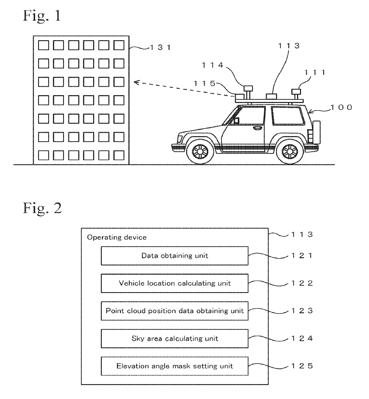
[0030]Here, a case of obtaining three-dimensional information surrounding a vehicle in real time and setting an elevation angle mask based on the three-dimensional information will be exemplified. FIG. 2 shows a block diagram of the operating device 113 that is equipped on the vehicle 100. The operating device 113 includes a data obtaining unit 121, a vehicle location calculating unit 122, a point cloud position data obtaining unit 123, a sky area calculating unit 124, and an elevation angle mask setting unit 125 as functional units. The operating device 113 has functions as a computer and includes a CPU, a RAM, a ROM, necessary storage devices, various kinds of operating devices such as an image processing integrated circuit, and various kinds of interfaces. The functional units of the operating device 113 may be constructed of software or may be constructed of dedicated hardware. For example, each of the functional units shown in FIG...

second embodiment

2. Second Embodiment

[0049]Here, a case of judging whether there is a blocking object between the antenna and the navigation satellite and selecting an appropriate navigation satellite will be exemplified.

Structure

[0050]FIG. 5 shows a block diagram of an operating device 113 that is different from the type of the operating device 113 shown in FIG. 2. This operating device 113 includes a data obtaining unit 121, a vehicle location calculating unit 122, a point cloud position data obtaining unit 123, a directional line setting unit 126, an overlap judging unit 127, and a weighting setting unit 128. Here, the data obtaining unit 121, the vehicle location calculating unit 122, and the point cloud position data obtaining unit 123 are the same as those in the case shown in FIG. 2.

[0051]The directional line setting 126 selects a line that connects the antenna 111 and a captured navigation satellite as a directional line. The directional line is set as described below. First, the position of...

third embodiment

3. Third Embodiment

[0066]The processing relating to the navigation satellite, which is unsuitable for use because the navigation satellite is blocked by a building or the like, may be performed in postprocessing. In this case, GNSS data that is received from the navigation satellites while the vehicle travels is stored as it is. At this time, inappropriate navigation satellites are not detected, and the original received data is linked with the time information as it is and is then stored in a storage device such as a semiconductor memory, a hard disk drive, or the like. On the other hand, positioning of the vehicle 100 is performed in real time by using the GNSS data, and three-dimensional point cloud position data is obtained by the laser scanner 115 at the same time.

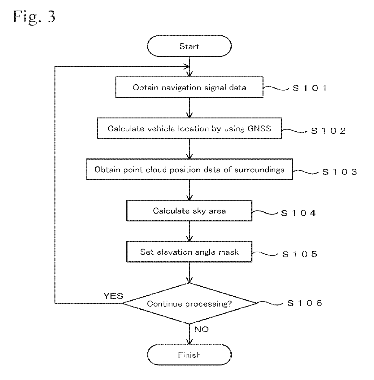
[0067]Then, the obtained data is processed as described below at a later timing. Here, the processing shown in FIG. 3 is performed by using the GNSS data and the three-dimensional point cloud position data. By perform...


PUM


Abstract

A navigation signal processing device includes circuitry configured to perform positioning of an antenna based on navigation signals received by the antenna from navigation satellites, set an elevation angle mask that causes inhibition of utilization of the navigation signals that are received from a specific angle range as viewed from the antenna in the positioning of the antenna, and obtain three-dimensional point cloud position data that includes data of multiple points of the surroundings as viewed from the antenna. The multiple points are obtained by a laser scanner or a stereoscopic camera and have determined three-dimensional coordinates. The circuitry is further configured to set the elevation angle mask that causes inhibition of utilization of the navigation signals that are received from a straight line direction connecting the antenna and each of the multiple points of the three-dimensional point cloud position data as viewed from the antenna.

Description

BACKGROUND OF THE INVENTION[0001]Technical Field[0002]The present invention relates to a positioning technique using a GNSS (Global Navigation Satellite System).[0003]Background Art[0004]In a GNSS, positioning signals are received from navigation satellites, and positions are measured. The positioning using a GNSS tends to be performed with less precision due to reflected waves (multiple paths) that are received even though direct waves of positioning signals are blocked off by buildings, trees, etc. The GNSS can be executed by setting an elevation angle mask so as not to use positioning signals from lower angles at which reflected waves tend to be generated (for example, refer to Japanese Unexamined Patent Application Laid-Open No. 2013-083480). A technique relating to this technique is disclosed in Japanese Unexamined Patent Application Laid-Open No. 2006-162563. In this technique, a database of three-dimensional geographical information of buildings and the like is used for judgi...

Claims


Application Information

Patent Timeline
Patent Type & Authority Patents(United States)
IPC IPC(8): G01S19/42
CPCG01S19/42G01S19/428G01S19/28
Inventor SASAKI, YOUITO, TADAYUKI
Owner KK TOPCON
Why Eureka
Try Eureka