Rotating electrical machine coil

a technology of electrical machines and coils, which is applied in the direction of windings insulation materials, dynamo-electric components, dynamo-electric machines, etc., can solve the problem that the cooling performance cannot be improved so much, and achieve the effect of improving the cooling performance and improving the thermal conductivity

Active Publication Date: 2019-04-02
MEIDENSHA ELECTRIC MFG CO LTD
View PDF26 Cites 2 Cited by
  • Summary
  • Abstract
  • Description
  • Claims
  • Application Information

AI Technical Summary

Benefits of technology

[0032]According to the present invention, it is possible to improve the thermal conductivity, in particular, of the coil end portion of a rotating electrical machine coil, and thereby improve the cooling performance of not only the coil end portion but also the entire electrical machine including the coil side portion.

Problems solved by technology

Without cooling, the temperature would rise by at least 100° C. or more, deteriorating a resin material included in the generator, which causes a failure.
Since the coil end portion is not in contact with a metal (iron core), and in addition, has a problem that the adhesion between the coil insulation materials is poor, which tends to cause a gap, the cooling performance cannot be improved so much even if an insulation material having a high thermal conductivity is used at the coil end portion.

Method used


Image

  • Rotating electrical machine coil
  • Rotating electrical machine coil
  • Rotating electrical machine coil

Examples


example

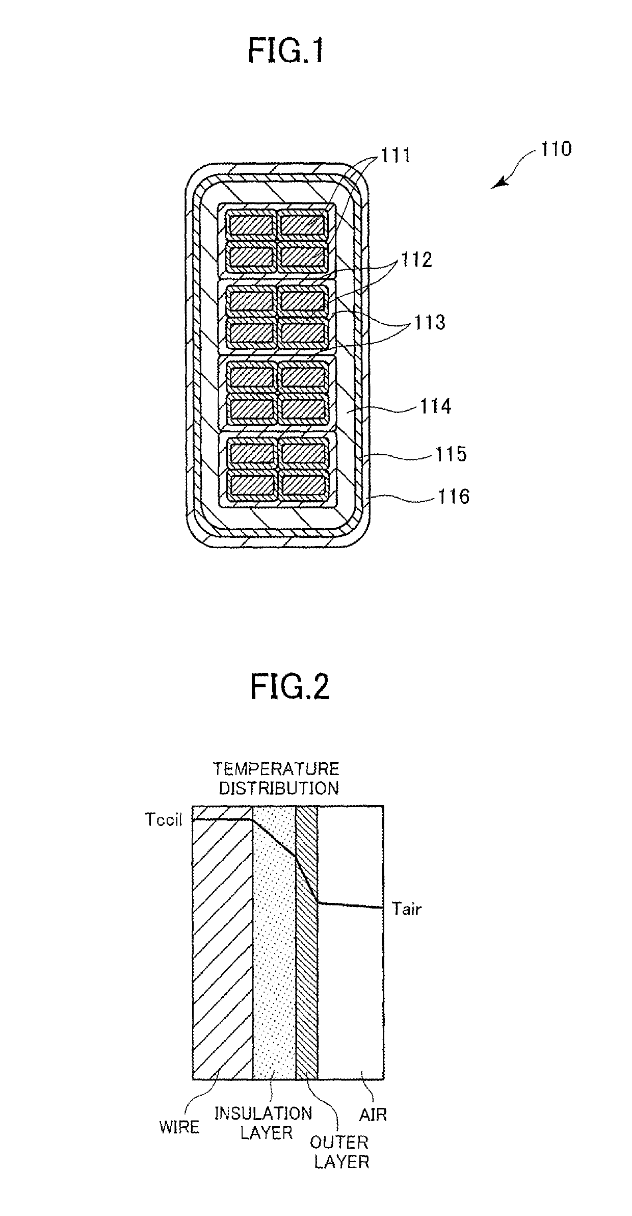
[0039]FIG. 1 is a cross-sectional view illustrating a coil end portion of a stator coil 110 of a generator according to the present invention. As illustrated in the figure, formed on the outer circumferential surface of a wire 111 is a wire insulation layer 112. Four wires 111, each covered with the wire insulation layer 112, form a wire bundle. Formed on the outer circumferential surface of this wire bundle (portions of the wire insulation layers 112 corresponding to the outer circumferential surface of the wire bundle) is an interlayer insulation layer 113.

[0040]A wire group is formed by four wire bundles juxtaposed together, each bundle having the interlayer insulation layer 113 formed thereon. Formed on the outer circumferential surface of this wire group (portions of the interlayer insulation layers 113 corresponding to the outer circumferential surface of the wire group) is a main insulation layer 114. In other words, the main insulation layer 114 is arranged on the outer circ...


PUM


Abstract

According to the present invention, a wire insulation layer (112) and an interlayer insulation layer (113) are formed on a wire (111). A main insulation layer (114) is formed by winding highly thermally conductive mica tape. A first outer insulation layer (115) formed from heat-shrinking material and a second outer insulation layer (116) formed from a highly thermally conductive resin are formed at a coil end section. Due to this configuration, the thermal conductivity of the coil, particularly of the coil end section, is improved, thereby enabling improved cooling performance.

Description

TECHNICAL FIELD[0001]The present invention relates to a rotating electrical machine coil and is devised by employing a unique material as an insulation material for the coil insulation layer such that the cooling performance, in particular, of the coil end portion is improved.BACKGROUND ART[0002]Since a large current of several thousand amperes or more flows in the generator during operation, the generator is cooled typically using a refrigerant such as air, hydrogen, and water, in order to prevent overheating. Without cooling, the temperature would rise by at least 100° C. or more, deteriorating a resin material included in the generator, which causes a failure. For this reason, the cooling is a very important technique.[0003]Here, a structure of a conventional stator coil of a generator will be described.[0004]FIG. 4 is a cross-sectional view illustrating a stator coil 10 of a generator according to a conventional technique. As illustrated in the figure, a wire insulation layer 12...

Claims


Application Information

Patent Timeline
Patent Type & Authority Patents(United States)
IPC IPC(8): H02K3/40H02K3/34H02K3/30
CPCH02K3/40H02K3/30H02K3/34H02K2213/03H02K2203/15
Inventor AKASHI, YASUYUKITADOKORO, TAEMI
Owner MEIDENSHA ELECTRIC MFG CO LTD
Why Eureka
Try Eureka