Method of fastening structural metal reinforcement on a portion of a gas turbine blade made of composite material, and an injection mold for performing such a method

a technology of composite materials and metal reinforcement, which is applied in the direction of efficient propulsion technologies, machines/engines, liquid fuel engines, etc., can solve the problems of difficult to achieve satisfactory thickness of adhesive over all contact areas between metal reinforcement and blades, and the inability to ensure equal thickness of adhesive layer under constant fabrication conditions, etc., to achieve good control over the final thickness of the layer, good control of the final thickness, and great freedom of us

Active Publication Date: 2019-04-16
SN DETUDE & DE CONSTR DE MOTEURS DAVIATION S N E C M A
View PDF8 Cites 2 Cited by
  • Summary
  • Abstract
  • Description
  • Claims
  • Application Information

AI Technical Summary

Benefits of technology

[0009]The fastening method of the invention presents the advantage of being based on a method of filling with resin by using a liquid technique of the liquid composite molding (LCM) type, and more particularly a method of injecting resin of the resin transfer molding (RTM) type or of the vacuum assisted resin transfer molding (VARTM) type so as to bond the structural metal reinforcement adhesively to the blade. Such methods are themselves well known, thus making it possible to ensure good control over the method of fastening the structural metal reinforcement. With this method, it is possible in particular to have good control over the final thickness of the layer of adhesive at all points in the area of contact between the metal reinforcement and the blade. This makes it easy to obtain reproducible adhesive bonding of metal reinforcement on all of the blades of a gas turbine.
[0010]The blade may be positioned horizontally or vertically in the injection mold. Likewise, the blade may be positioned in part or in full in the injection mold. As a result, the method of the invention presents great freedom in use.
[0011]Preferably, the method further comprises establishing a vacuum in the gap between the structural metal reinforcement and the portion of the blade on which the structural metal reinforcement is to be fastened prior to injecting the adhesive. Establishing a vacuum makes it possible to ensure that the adhesive is distributed in completely uniform manner in the gap.

Problems solved by technology

Nevertheless, adhesively bonding a piece of structural metal reinforcement raises several problems.
In particular, it is difficult to obtain a satisfactory thickness of adhesive over all of the areas of contact areas between the metal reinforcement and the blade.
Furthermore, with varying viscosity between different batches of adhesive, it is impossible to ensure equal thickness for the layer of adhesive under constant fabrication conditions.

Method used


Image

  • Method of fastening structural metal reinforcement on a portion of a gas turbine blade made of composite material, and an injection mold for performing such a method
  • Method of fastening structural metal reinforcement on a portion of a gas turbine blade made of composite material, and an injection mold for performing such a method

Examples


Embodiment Construction

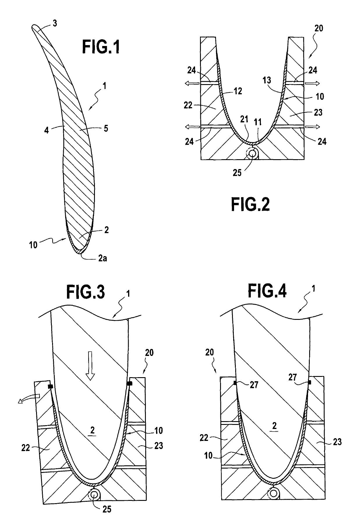
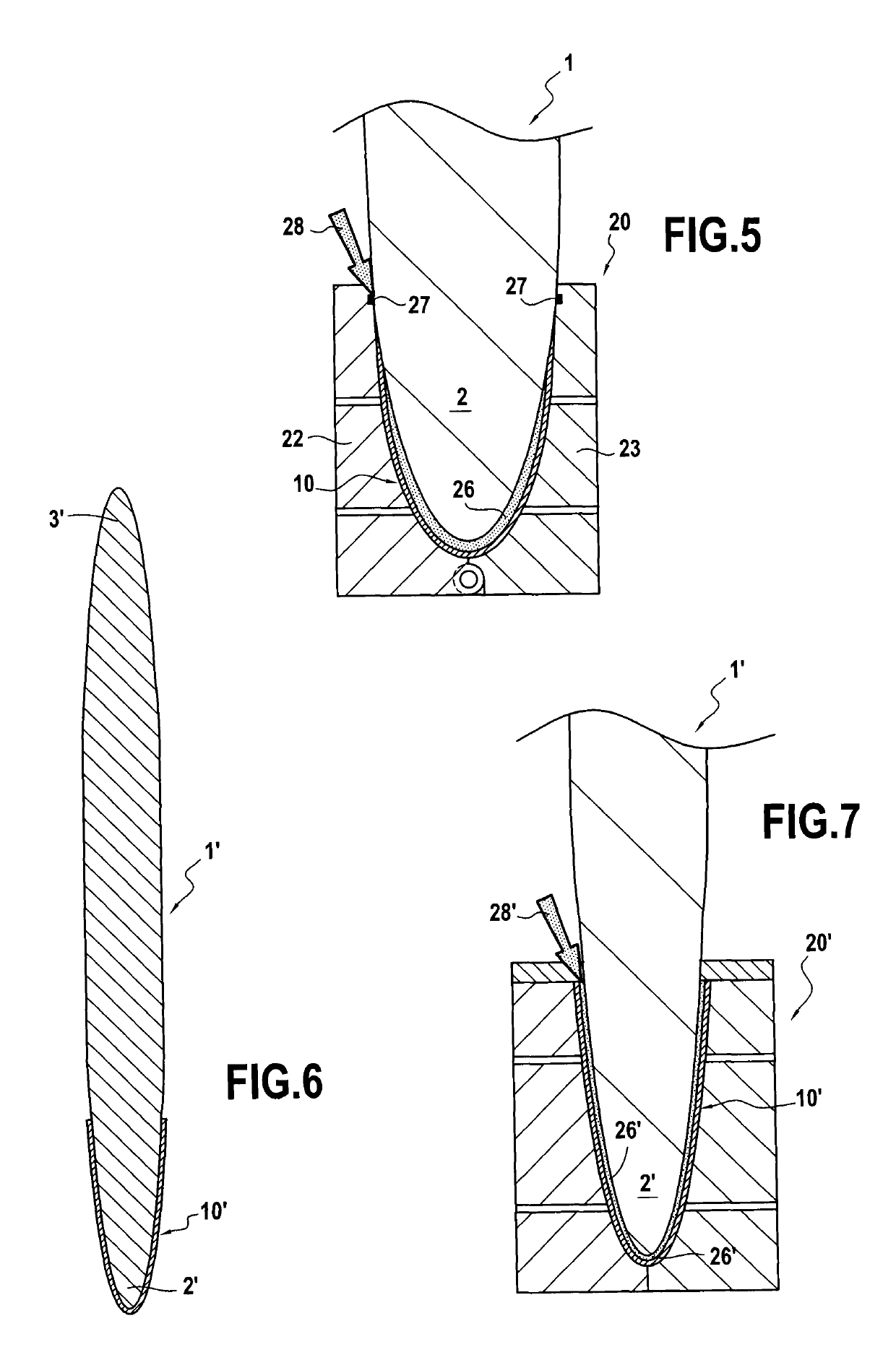
[0020]The invention applies to any gas turbine blade made of composite material for an aeroengine, and in particular it relates to turbine engine fan blades as shown in section in FIG. 1.

[0021]In known manner, the fan blade 1 presents an airfoil surface that extends in particular between a leading edge 2 and a trailing edge 3. The airfoil surface of the fan blade also has a pressure side face 4 and a suction side face 5 that form the side faces of the blade interconnecting the leading edge and the trailing edge.

[0022]The fan blade 1 is made of composite material with fiber reinforcement densified by a matrix. For example, the blade may be made by three-dimensionally weaving a fiber preform and impregnating the preform with a matrix, the assembly being formed by molding using a vacuum assisted resin injection method of the VARTM type.

[0023]The fan blade 1 has structural metal reinforcement 10 that is adhesively bonded to its leading edge 2 and that extends both axially beyond the lea...


PUM

PropertyMeasurementUnit
temperatureaaaaaaaaaa
adhesiveaaaaaaaaaa

Abstract

A method of fastening structural metal reinforcement on a portion of a gas turbine blade made of composite material and an injection mold for performing the method, the method including positioning the structural metal reinforcement in an injection mold, positioning the portion of the blade onto which the structural metal reinforcement is to be fastened in the injection mold, the portion of the blade and the structural metal reinforcement being positioned relative to each other in their final relative position while leaving between them a gap, injecting adhesive into the gap between the structural metal reinforcement and the portion of the blade onto which the structural metal reinforcement is to be fastened, and polymerizing the adhesive.

Description

BACKGROUND OF THE INVENTION[0001]The present invention relates to the general field of aeroengine gas turbine blades that are made of composite material and that have a leading edge and / or a trailing edge fitted with metal structural reinforcement.[0002]A field of application of the invention is that of turbine engine fan blades or propeller blades. Another field of application of the invention is that of outlet guide vanes (OGV) for turbine engines.[0003]It is known for turbine fan blades that are made of composite material to be fitted with metal structural reinforcement extending over the full height of the blades and beyond their leading edges. The same applies to outlet guide vanes.[0004]Such structural reinforcement enables a set of composite blades to be protected against the fan being struck by a foreign body, such as a bird ingested by the engine, for example. In particular, the metal structural reinforcement serves to protect the leading edge (or the trailing edge) of a co...

Claims


Application Information

Patent Timeline
Patent Type & Authority Patents(United States)
IPC IPC(8): B29C65/54B32B38/18B32B37/16B32B37/12B29C45/26B29C45/16B29C45/14B29C65/48F01D5/28B29C65/00B29C65/78B23P15/04F04D29/32B32B38/00B29K305/00B29L9/00B29L31/08
CPCB29C65/542B29C45/14008B29C45/14065B29C45/1657B29C45/1671B29C45/2602B29C65/483B29C65/7847B29C66/12461B29C66/301B29C66/532B29C66/721B29C66/72141B29C66/742B29C66/81423B29C66/8221B29C66/83241B32B37/1284B32B37/16B32B38/1858F01D5/282F04D29/324B23P15/04Y02T50/673B29C65/4835B29C2045/14155B29C2045/1664B29K2305/00B29L2009/003B29L2031/08B29L2031/082B32B2038/0076B32B2305/08B32B2311/18B32B2603/00F01D5/288F05D2240/303Y02T50/672B29C66/53Y02T50/60B29C70/48
Inventor GODON, THIERRYDAMBRINE, BRUNO JACQUES GERARDVARIN, FRANCK BERNARD LEON
Owner SN DETUDE & DE CONSTR DE MOTEURS DAVIATION S N E C M A
Why Eureka
Try Eureka