Motor and rotor
a rotor and motor technology, applied in the direction of magnetic circuit rotating parts, shielding from electromagnetic fields, magnetic circuit shape/form/construction, etc., can solve the problems of lowering detection accuracy, deteriorating power output characteristics, and magnetic flux likely to leak to the housing side, so as to achieve the effect of suppressing leakage flux
- Summary
- Abstract
- Description
- Claims
- Application Information
AI Technical Summary
Benefits of technology
Problems solved by technology
Method used
Image

Examples
first embodiment
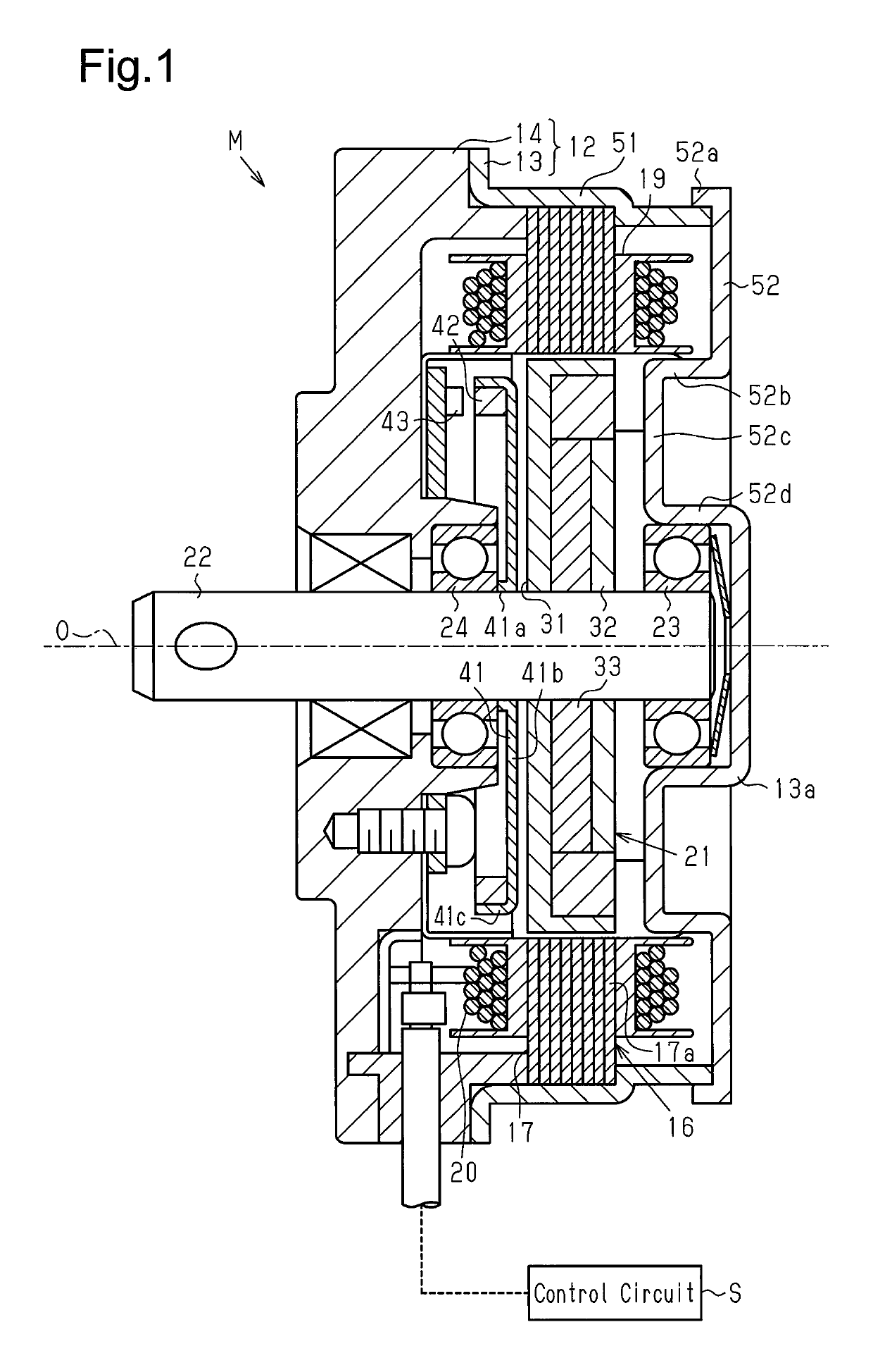
[0030]Hereafter, a motor will be described with reference to FIGS. 1 to 4.
[0031]As shown in FIG. 1, a case 12 for a brushless motor M as a motor includes a yoke housing 13 formed into a substantially cylindrical shape with a bottom part, and an end plate 14 as a cover part which closes an opening part of the yoke housing 13 and is made of a resin material which is a non-magnetic body.
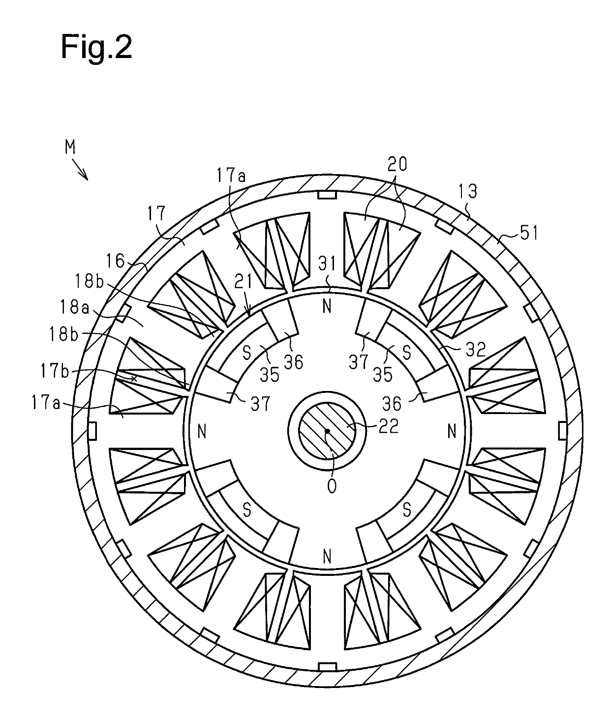
[0032]As shown in FIG. 1, a stator 16 is fixed to an inner peripheral surface of the yoke housing 13. The stator 16 includes a stator core 17 having a plurality of teeth 17a extending to the radially inner side, and a winding 20 wound around a tooth 17a of the stator core 17 with an insulator 19 interposed therebetween. Supply of a drive current to the winding 20 from an external control circuit S causes the stator 16 to generate a rotating magnetic field.
[0033]As shown in FIG. 2, the stator core 17 of the first embodiment has twelve teeth 17a arranged in the circumferential direction. Therefore, the nu...
second embodiment
[0065]Hereafter, the Lundell-type motor will be described.
[0066]As shown in FIGS. 8 to 10, a brushless motor M of the second embodiment, which is a Lundell-type motor, is a motor to be used for a position control device disposed in a vehicle engine room, particularly for a variable valve timing device to be linked to an engine.
[0067]As shown in FIGS. 8 to 11, the brushless motor M includes a motor case 101. The motor case 101 includes a tubular front housing 102 which is made of a magnetic body and is formed into a tubular shape having a cover part, and an end frame 103 which is made of aluminum (non-magnetic body) and closes an opening part of the tubular front housing 102.
[0068]The brushless motor M is configured such that a stator 105 is fixed to an inner peripheral surface of the tubular front housing 102, and a rotor 107 having a so-called Lundell-type structure, which is secured to the rotary shaft 106 and integrally rotates with the same rotary shaft 106, is arranged on the i...
third embodiment
[0131]Hereafter, brushless motor will be described with reference to FIGS. 14 to 16.
[0132]As shown in FIG. 14, a brushless motor M as a motor is configured such that a stator 202 is fixed on the inner peripheral surface of a motor housing 201, and on the inner side of the stator 202, a rotor 204 having a so-called Lundell-type structure is disposed. The rotor 204 is fixed to a rotary shaft 203 and integrally rotates with the rotary shaft 203. The rotary shaft 203, which is a shaft made of a non-magnetic stainless steel, is supported by a bearing, which is not shown and provided in the motor housing 201, so as to be rotatable with respect to the motor housing 201.
[0133]The stator 202 includes a stator core 210 having a cylindrical shape. The outer peripheral surface of the stator core 210 is fixed to the inner peripheral surface of the motor housing 201. On the inner side of the stator core 210, a plurality of teeth 211, which are formed along an axial direction and disposed at equal...
PUM
| Property | Measurement | Unit |
|---|---|---|
| non-magnetic | aaaaa | aaaaa |
| magnetic | aaaaa | aaaaa |
| cylindrical shape | aaaaa | aaaaa |
Abstract
Description
Claims
Application Information
 - R&D
- Intellectual Property
- Life Sciences
- Materials
- Tech Scout
- Unparalleled Data Quality
- Higher Quality Content
- 60% Fewer Hallucinations
Browse by: Latest US Patents, China's latest patents, Technical Efficacy Thesaurus, Application Domain, Technology Topic, Popular Technical Reports.
© 2025 PatSnap. All rights reserved.Legal|Privacy policy|Modern Slavery Act Transparency Statement|Sitemap|About US| Contact US: help@patsnap.com