Cloud encoding system

a cloud and encoding technology, applied in the field of cloud encoding systems, can solve the problems of scarce efficiency, n-times greater transmission resources, and no common standard for serving all the devices connected to the network, so as to improve reduce bandwidth, and optimize computing and data transmission resources

Active Publication Date: 2019-04-23
SKY ITALIA SRL
View PDF20 Cites 0 Cited by
  • Summary
  • Abstract
  • Description
  • Claims
  • Application Information

AI Technical Summary

Benefits of technology

[0084]A technical advantage of the present invention consists in a considerable reduction in the bandwidth that is needed for the broadcaster to send the content / channel to users over the Internet, because the operations of encoding / compressing all the levels distributed at a lower quality than level 1 are performed in the cloud in a distributed manner, thus optimising computing and data transmission resources.
[0085]Further technical advantages are that content is uploaded to the broadcaster using a greatly reduced bandwidth and the amount of computing resources used for transcoding depends on the real needs generated by user demands.
[0086]Moreover, the system reveals to be conducive to an efficient content distribution, over the Internet, to devices of different form and nature, with the extra advantage of enabling savings in transmission bandwidth since the resources necessary to generate the formats for distribution over the Internet are allocated to the cloud.
[0087]In addition, one obtains a result that is comparable to when compression is managed starting from content / channels at a high bit rate (the highest available in production), but the compression chain / process handled by the content provider or media company is simplified, thus reducing operating and infrastructural costs.
[0088]If the second encoding implies a compression, a further technical advantage of the present invention consists in a reduction in the computing resources and bandwidth used during this step, since previously pre-compressed content needs not be decompressed, but can rather be directly processed.
[0089]In the present description, reference has been made to means, such as, for example, an encoding means, to indicate any concentrated device (i.e. distinct or separate unit) or distributed device (i.e. constructed from a number of components connected to one another and physically near or remote from one another); the means, be they concentrated or distributed, can moreover be made up of hardware, software or a combination thereof. Moreover, terms such as encoding means, transmission means, etc. can also be replaced by encoder, transmitter, etc.

Problems solved by technology

Unfortunately, there exists no common standard for serving all the devices connected to the network (each of which with a different screen and resolution).
Therefore, being able to compress audiovisual content in the best possible way by containing the bit rates for each level while ensuring the highest possible quality represents a technical challenge for distribution over the Internet.
Therefore, the transmission resources necessary (and hence the costs) are n times greater than if a single content item / channel were to be sent over the Internet.
Recently, numerous solutions have been made available (for example by Amazon and Verizon) which involve compressing content directly over the Internet (via cloud computing), avoiding the need for the service provider (media company) to manage a complex compression chain; however, such solutions entail sending content over the network in a scarcely efficient manner and usually involve a complete outsourcing of transcoding services to the cloud provider, taking away all control from the media company.
However, these solutions still present some disadvantages from a technical viewpoint.
The most evident of these disadvantages is that the upload of the content / channel to the Internet occurs at a high bit rate, e.g. 50-100 Mbps or more (up to 3 Gbps or 10 Gbps for live broadcasts), as mentioned above.
The solution is thus not efficient since it requires large transmission resources (and thus implies high costs) and does not allow the media company to have any control over the distribution chain.
Even if pre-compressed to 10 Mbps (i.e. to a level that is not too low), such content generally loses a great deal of information (compared to the 50-100 Mbps of a video source with HD quality); therefore, the subsequent multiformat / bit rate compression operation will be less efficient and of lower quality (even at the same bit rate) than that performed starting from content or channels with HD production quality.

Method used


Image

  • Cloud encoding system
  • Cloud encoding system
  • Cloud encoding system

Examples


first embodiment

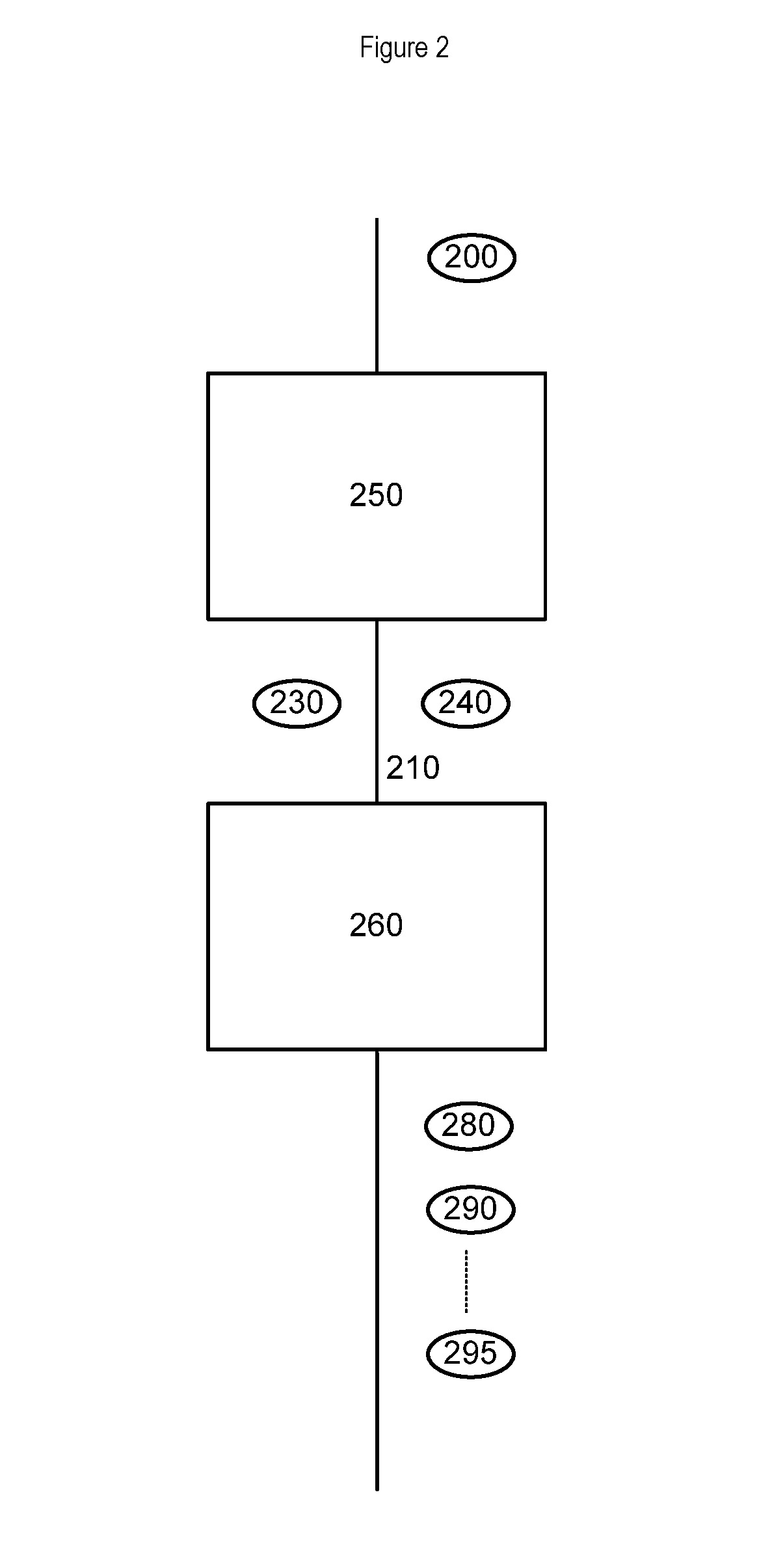
[0066]As can be seen in FIG. 2, according to an optional variant of the first embodiment, the system can be configured in such a way that the second encoding means 260 produces a multitude (plurality) of second encodings 280, 290, . . . 295. The characteristics (such as, for example, one or more among: the bit rate, resolution, format or other characteristics) of each of the second encodings obtained from the second encoding means 260 are determined by the configuration parameters which may be contained in the encoding information. It should be noted that each of the encoded signals produced is characterised by a corresponding predetermined property, wherein the property indicates the characteristics or attributes of the second encoded signal that is output, such as, for example, one or more of the following: desired resolution, level of compression, bit rate, format, etc. . . .

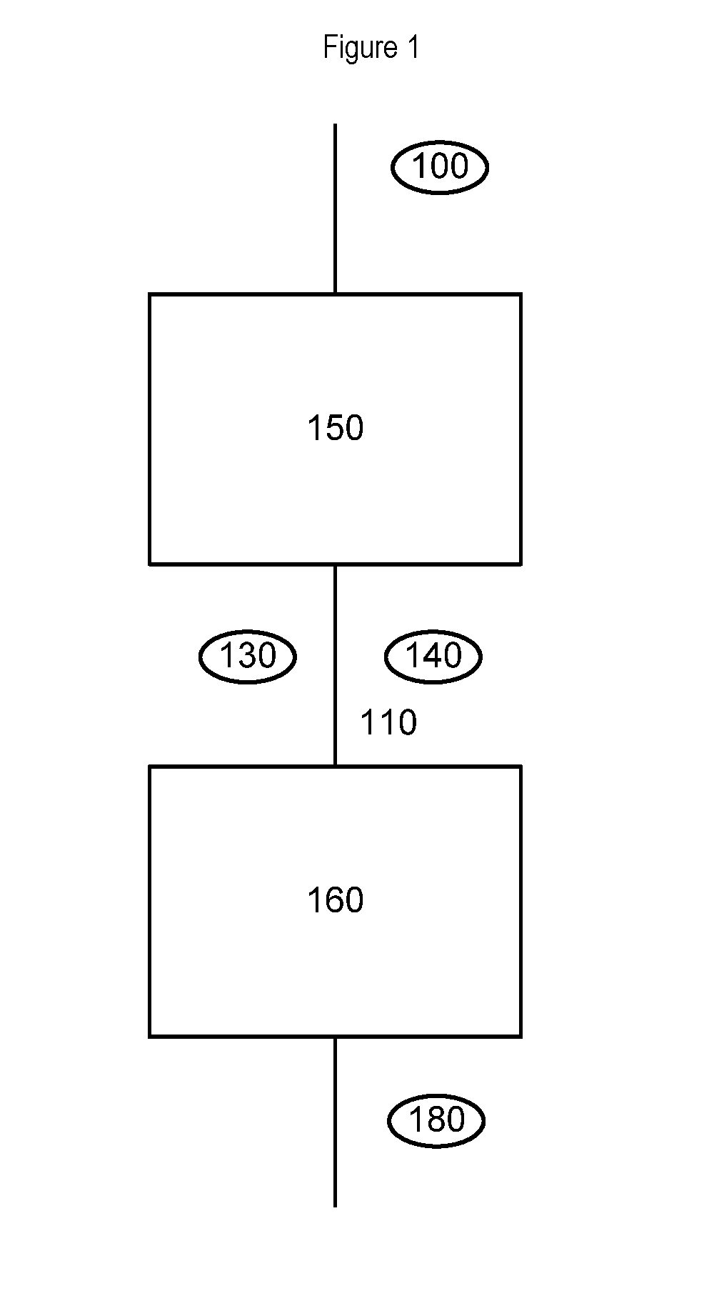
[0067]In an optional variant of the present invention, the second encoding means 160 carries out one of th...

third embodiment

[0073]FIG. 4 shows a block diagram according to the present invention, where a device 350 encodes an ungrouped signal 310 into a grouped signal 390, said ungrouped signal 310 comprising at least a video service. The device 350 comprises encoding means 355 configured to execute a first encoding of said ungrouped video signal 310 into a first encoded grouped signal and to associate encoding information with said first encoded signal. The encoding information contains information obtained during the first encoding process and relating thereto and can contain configuration information for the execution of a second encoding by a further device. The encoding information can optionally contain information relating to the property of the second encoded signal that is output (or each property corresponding to a plurality of second encoded output signals). The device 350 further comprises a transmission means 370 for transmitting said first encoded signal and encoding information to a further...


PUM


Abstract

A system (and corresponding method and devices) for encoding an ungrouped signal into a plurality of grouped signals, wherein the ungrouped signal comprises at least a video service. The system further comprises:a first encoding means provided in a production system configured to execute a first encoding of the ungrouped video signal into a first encoded grouped signal and to associate encoding information with the first encoded signal;a second encoding means provided in a distribution system, wherein the second encoding means is separate from said first encoding means and is configured to execute a plurality of second encodings so as to correspondingly obtain the plurality of grouped signals, each of the plurality of grouped signals characterized by a corresponding predetermined property, wherein the second encodings are performed on the basis of said first encoded signal using the encoding information;a connection means configured to transmit the encoding information from the first encoding means to the second encoding means, wherein the encoding information comprises information on the first encoding.

Description

RELATED APPLICATIONS[0001]This application is a U.S. National Phase Application under 35 U.S.C. 371 of International Application No. PCT / IB2014 / 002095 filed Oct. 14, 2014, which was published on Apr. 23, 2015, under International Publication Number WO 2015 / 056075 A1, which claims the benefit of Italian Patent Application No. MI2013A001710 filed on Oct. 15, 2013. These applications are incorporated herein by reference in their entirety.FIELD OF THE INVENTION[0002]The present invention relates to a system for encoding ungrouped signals into grouped signals in two steps.BACKGROUND OF THE INVENTION[0003]With the advent of the Internet the transmission of audio and video content, in a linear or non-linear mode (e.g. VOD, catch-up, etc . . . ), has undergone enormous expansion and the dissemination of terminals that can receive audiovisual signals (smartphones, tablets, PCs, connected devices, etc . . . ) has likewise increased. Unfortunately, there exists no common standard for serving a...

Claims


Application Information

Patent Timeline
Patent Type & Authority Patents(United States)
IPC IPC(8): H04N7/173H04N21/2343H03M7/30H04N21/222H04N21/2662H04N21/61
CPCH04N21/23439H03M7/6011H03M7/6017H03M7/6064H04N21/222H04N21/234309H04N21/234363H04N21/2662H04N21/6125
Inventor BERTOLOTTI, MASSIMOSONNATI, FABIO
Owner SKY ITALIA SRL
Why Eureka
Try Eureka