Scheduling function calls

a function call and function technology, applied in the field of data processing, can solve the problems of not being able to handle all of the function calls right away, not being able to solve the problem of processing processing time being busy, and having very little spare capacity, so as to improve energy efficiency, improve lateness, and high processing efficiency

Active Publication Date: 2019-04-23
ARM IP
View PDF35 Cites 0 Cited by
  • Summary
  • Abstract
  • Description
  • Claims
  • Application Information

AI Technical Summary

Benefits of technology

[0010]By defining a target time window for every function call in the queue, the target time window can then be used as the primary scheduling mechanism, rather than a mere secondary hint. This is useful because, unlike priority information, the target time window provides scheduling information which can be used for scheduling both when processor utilization is high (for prioritizing between different function calls) and when processor utilization is low (for deciding how to schedule function calls to improve energy efficiency). This approach is counter intuitive since the target time window information has typically been regarded as an optional additional annotation rather than a primary scheduling mechanism in its own right. Also, unlike some previous systems which have specific modes which prioritize different sorts of function calls, the present technique provides an improved scheduling mechanism because it may cope flexibly with a greater variety of circumstances than just a limited set of modes, and because it allows for a simpler application programming interface (API), which governs how software components interact with each other.
[0011]The scheduler can infer a priority of a function call from the target time window identified for the function call. For example, if a particular function call is associated with a long target time window, indicating that it is acceptable to process the function call at any time during a long time period, then this function call can be determined to be of relatively low priority. Conversely, a function call associated with a narrow time window can be considered to have higher priority. Therefore, the target time window can implicitly indicate the priority of function calls, so that it is not necessary to provide an explicit priority indication for each function call. This reduces the amount of information that needs to be provided by applications for characterising the function calls to the scheduler, and so simplifies development of applications. An application developer may only need to specify the target time window for a function call rather than defining multiple pieces of scheduling information as is common in previous scheduling schemes.
[0016]The prioritization and reordering of the function calls discussed above is most useful when processor utilization is high. When the processor is relatively busy, it is more likely that the processor cannot handle all function calls within their respective target time windows, and in this case, it is useful to perform prioritization or reordering based on the target time window to improve lateness, and hence processing performance. The target time window identified for each function call helps the scheduler determine which are the most important functions to process first.
[0017]On the other hand, when processor utilization is low, then the target time window can be useful to improve energy efficiency. If the processor has to process a number of function calls which are spread over a period of time, then it may be more efficient for those function calls to be coalesced so that they are processed one after the other, rather than having some inactive periods in between processing the function calls. By coalescing at least two function calls, it is possible to reduce an overall time for which the processor is active, and / or to reduce an overall measure of energy consumption by the processing circuitry. The scheduler may determine whether, if at least two function calls were coalesced, each of the function calls could still be processed within their respective target time windows. If this is possible, then the scheduler may coalesce the function calls to save energy (for example, by reducing processor idle time or the number of times the processor switches between an active mode and sleep mode).
[0032]The present technique may be implemented in any type of data processing system requiring scheduling of function calls. However, as the target time window information is useful for scheduling both at high processor utilization and at low processor utilization, the present technique is particularly useful for systems expected to be fully active or almost fully active for some periods and also expected to be idle for significant periods of time. For example, there is an increasing use of wearable processing devices, such as a smart watch or jewelry having some processing capability. When such a device is being used by the user, then the processor may be busy and may have very little spare capacity. However, at other times when the user is wearing the device but not actively using it, the processor may be doing very little. For example, the watch may be doing nothing other than incrementing the displayed time once per minute. Therefore, there may be significant periods of low processor utilization, and so steps to improve energy efficiency may be useful. Hence, defining the target time window information for each queued function call is useful in both scenarios, and so the present technique is particularly suited to wearable processing devices.

Problems solved by technology

There may be various competing sources of function calls, such as applications or interrupt handlers, and it may not be possible to handle all of the function calls right away.
While the scheduler may aim to schedule each function call for processing within its corresponding target time window, in practice this may not be possible as there may be more function calls to be processed within a given time frame than can be handled using the available processing capacity of the processing circuitry.
This is not possible with priority information since the priority information does not provide any information about whether coalescing is acceptable (the priority information does not give any indication of whether it is allowable for the function calls to be processed earlier or later than the preferred time).
When such a device is being used by the user, then the processor may be busy and may have very little spare capacity.
However, at other times when the user is wearing the device but not actively using it, the processor may be doing very little.

Method used


Image

  • Scheduling function calls
  • Scheduling function calls
  • Scheduling function calls

Examples


Embodiment Construction

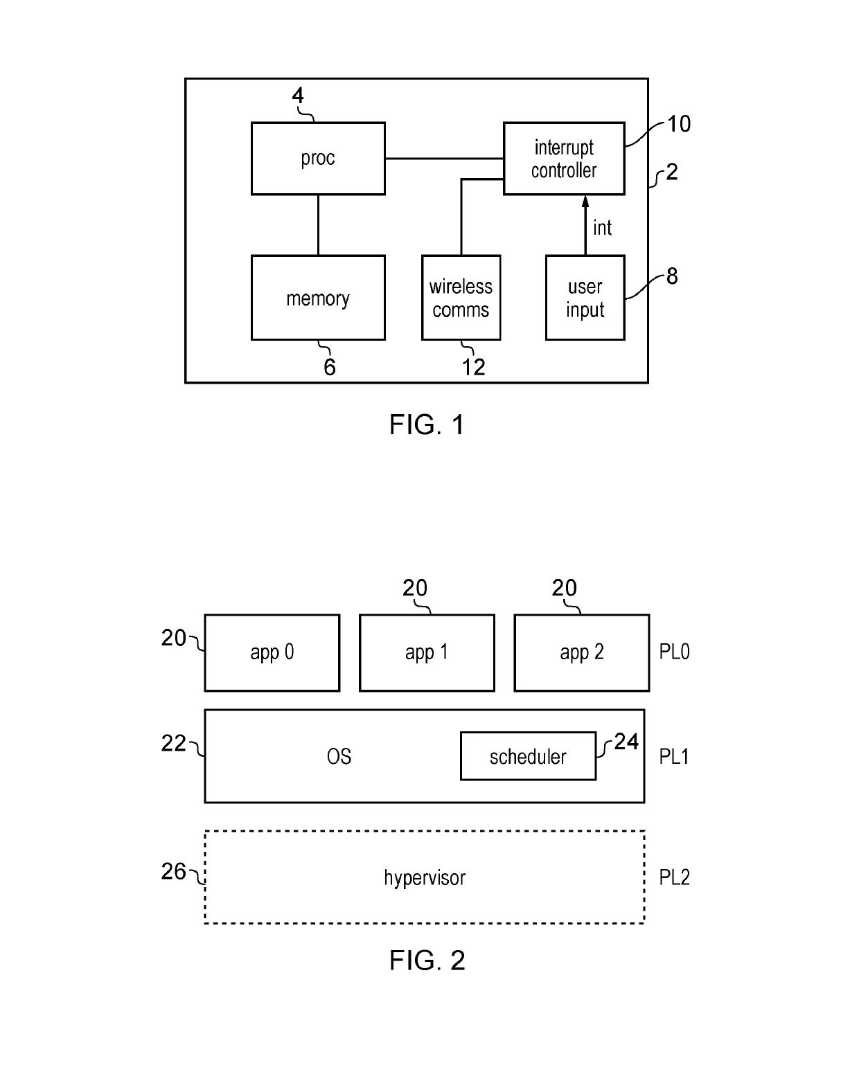
[0052]FIG. 1 schematically illustrates a data processing apparatus 2 comprising processing circuitry 4 for processing data. The processing circuitry 4 may comprise one processor core or multiple processor cores. The apparatus 2 has a memory 6 for storing data and instructions to be processed by the processor 4. A user input interface 8 is provided, for example including input buttons, a touch screen, or other input devices. An interrupt controller 10 is provided to receive interrupts and trigger corresponding interrupt handling to be processed by the processor 4. For example, when the user presses a button on the data processing apparatus 2, then an interrupt is triggered and the interrupt controller 10 triggers the processing circuitry 4 to perform a corresponding interrupt handling routine for carrying out some processing operations associated with the pressed button. The processing apparatus 2 also has an optional wireless communication unit 12 for communicating with other device...


PUM


Abstract

A data processing apparatus has a scheduler which maintains a queue of function calls to be scheduled for processing by processing circuitry. The scheduler identifies, for every function call in the queue, a target time window within which the processing circuitry should process the function call. The scheduler schedules processing of the function calls based on the target time window.

Description

RELATED APPLICATIONS[0001]The present application is a National Phase entry of PCT Application No. PCT / GB2014 / 053014, filed Oct. 7, 2014, which claims priority from GB Patent Application No. 1317753.0, filed Oct. 8, 2013, said applications being hereby incorporated by reference herein in their entirety.TECHNICAL FIELD[0002]The present invention relates to the field of data processing. More particularly, the invention relates to scheduling function calls for processing by processing circuitry.BACKGROUND ART[0003]Function calls may be used to trigger processing circuitry to perform a corresponding function. There may be various competing sources of function calls, such as applications or interrupt handlers, and it may not be possible to handle all of the function calls right away. Therefore, a scheduler may be provided to schedule which function calls are processed when by the processing circuitry. Such schedulers often use a prioritization scheme in which each function call has an as...

Claims


Application Information

Patent Timeline
Patent Type & Authority Patents(United States)
IPC IPC(8): H04W72/04H04L12/861H04B1/3827G06F9/48H04W72/12
CPCH04W72/0446G06F9/4881H04B1/385H04L49/90H04W72/1242Y02D10/24Y02D10/00G06F9/4887G06F9/5038H04W72/569
Inventor CROSBY, JAMES
Owner ARM IP
Why Eureka
Try Eureka