
Fluidized bed solid circulation system using pressure and density difference, fluidized bed reaction system having the same and solid circulation method

a circulation system and fluidized bed technology, applied in the direction of process control/regulation, chemical/physical/physicochemical processes, chemistry apparatus and processes, etc., can solve the problems of complicated system structure, increased gas cost, increased preheating and pressurization cost, etc., to increase the amount of solid particles, increase and reduce the density of solid particles

Active Publication Date: 2019-04-30
KOREA INST OF ENERGY RES
View PDF7 Cites 3 Cited by
  • Summary
  • Abstract
  • Description
  • Claims
  • Application Information

AI Technical Summary

Benefits of technology

The present invention provides a system for circulating solids between fluidized bed reactors using pressure and density difference. The system includes a plurality of pressure control valves, a lower loop seal, an upper loop seal, and a control part. The system can make a difference in pressure between the two reactors to circulate solids and increase the amount of solid particles even at lower pressure difference. The system can also include a plenum, distributor, and connection pipe to convey fluidizing gas and solids between the two reactors. The technical effect of the invention is to provide a more efficient and effective system for solid circulation and reaction in a fluidized bed reaction system.

Problems solved by technology

(e.g., when hydrogen is generated from the reaction, hydrogen can be separated using a steam by condensing in the discharged gas) In particular, when the two reactions occur at high temperature and high pressure, a conveyance gas with high temperature and high pressure should be injected, thereby incurring an additional cost for preheating and pressurization.
Also, a flow velocity of the fast fluidized bed should be increased to increase the amount of solid circulation, thereby increasing the cost for gas.
However, both methods using each of a solid discharge nozzle and a screw conveyer have complicated system structures and difficulties in selecting materials of the solid discharge nozzle, the solid riser, the solid recirculation pipe and the screw conveyor under high temperature and high pressure conditions.

Method used


Image

  • Fluidized bed solid circulation system using pressure and density difference, fluidized bed reaction system having the same and solid circulation method
  • Fluidized bed solid circulation system using pressure and density difference, fluidized bed reaction system having the same and solid circulation method
  • Fluidized bed solid circulation system using pressure and density difference, fluidized bed reaction system having the same and solid circulation method

Examples


Embodiment Construction

[0049]Exemplary embodiments will now be described with reference to the accompanying drawings to understand objects, other objects, features and advantages of the present invention. However, the present invention is not limited to the exemplary embodiments described herein and may be embodied in different forms. Rather, the exemplary embodiments are provided so that this disclosure will be through and complete, and will fully convey the idea of the present invention to those of ordinary skilled in the art.

[0050]In the description, when an element is referred to as being on the other element, it means that the element can be directly formed on the other element or interpose another element between them. Also, in the drawings, thickness of elements is exaggerated for easy understanding of technical features.

[0051]In the description, exemplary embodiments will be described with reference to a top plan view and / or an end view as an ideal exemplary view of the present invention. In the d...


PUM


Abstract

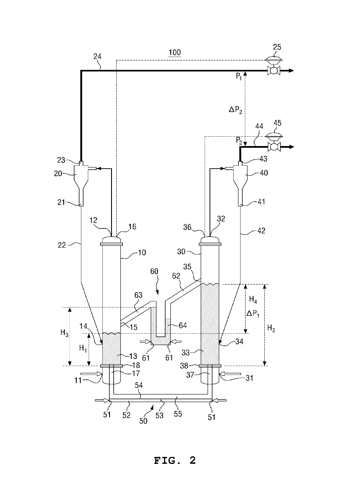
Disclosed is provided to overcome problems of conventional methods using each of a solid discharge nozzle and a screw conveyer. According to one exemplary embodiment of the present invention, a fluidized bed system is provided to circulate solids using pressure and density difference. More particularly, a fluidized solid circulation system using pressure and density difference is characterized by comprising: a first fluidized bed reactor; a second fluidized bed reactor; a first cyclone; a second cyclone; a first pressure control valve; a second pressure control valve; a lower loop seal; an upper loop seal; and a control part, thereby circulating the solids between the first fluidized bed reactor and the second fluidized bed reactor.

Description

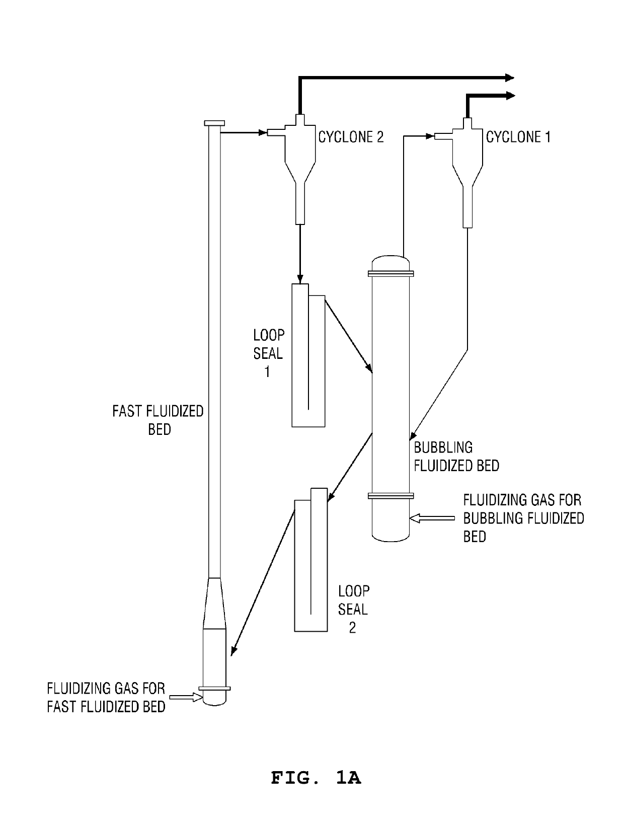
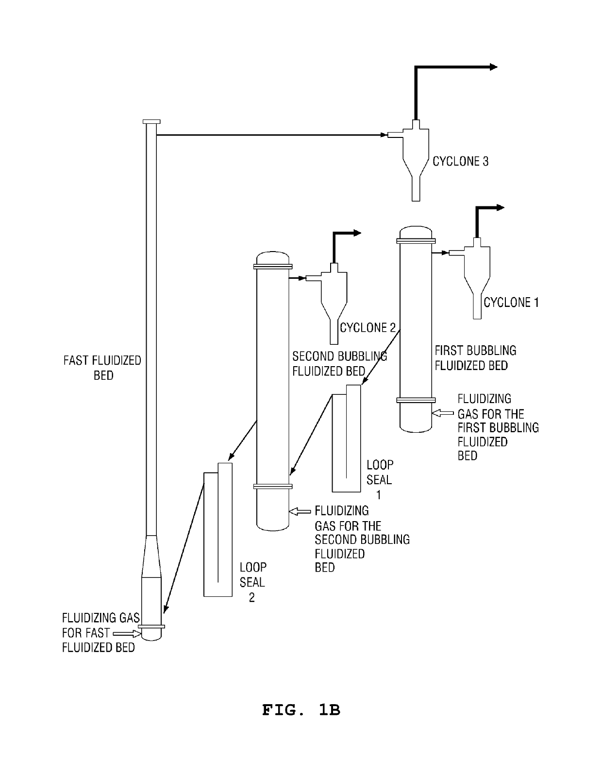
CROSS-REFERENCE TO RELATED APPLICATION[0001]The present application claims priority to and the benefit of Korean Patent Application No. 10-2017-0177435 filed in the Korean intellectual Property Office on Dec. 21, 2017, the entire contents of which are incorporated herein by reference.BACKGROUNDTechnical Field[0002]The present invention relates to a fluidized bed circulation system using pressure and density difference, a fluidized bed reaction system having the same and a solid circulation method.Description of the Related Art[0003]A gas-solid fluidized bed is a device that changes the behavior of solid particles to be similar to that of fluids by inserting solid particles into a fluidized bed reactor, injecting gases through a plenum and a gas distributor in a lower portion of the reactor, and floating the solid particles.[0004]Solid particles on the condition of a fixed bed or a packed bed are changed to be on the condition of bubbling fluidized bed (bubbles may not occur dependin...

Claims


Application Information

Patent Timeline
Patent Type & Authority Patents(United States)
IPC IPC(8): B01J8/26B01J8/00B01J8/18
CPCB01J8/26B01J8/1809B01J8/1818B01J8/0015B01J8/0055B01J2208/00752B01J2208/00539B01J2208/00761B01J8/28B01J8/388B01J2208/00584B01J8/1872B01J19/0006B01J19/0053B04C3/00
Inventor RYU, HO-JUNGLEE, DOYEONJIN, GYOUNG-TAEYI, CHANG-KEUNSHUN, DOWONPARK, JAEHYEONBAE, DAL-HEEJO, SUNG-HOLEE, SEUNG-YONGPARK, YOUNG CHEOLMOON, JONG-HOLEE, DONG-HO
Owner KOREA INST OF ENERGY RES
Learn More