Device for receiving microwave radiation

a microwave radiation and device technology, applied in the structure of radiating elements, individually energised antenna arrays, polarised antenna unit combinations, etc., can solve the problems of inability to operate the antenna, impair the reception quality, and multiple reflections between the circuit, so as to avoid multiple reflections and save material and weight, the effect of small siz

Active Publication Date: 2019-04-30
ROBERT BOSCH GMBH
View PDF13 Cites 1 Cited by
  • Summary
  • Abstract
  • Description
  • Claims
  • Application Information

AI Technical Summary

Benefits of technology

[0005]In accordance with the present invention, these multiple reflections may be avoid, and thus the present invention may improve the reception quality of the microwave antenna or the millimeter wave antenna. According to the present invention, this takes place in that multiple reflections of the received signals between the radome and the receiving antenna are avoided by using at least one polarization-rotating structure on the circuit board according to the present invention.
[0009]It may advantageously also be provided that the polarization-rotating structure is formed of a plurality of regularly arranged metal shapes on the circuit board of the receiving antenna. For effective suppression of multiple reflections which, depending on the operating state, may be caused by received waves impinging from different directions, it is advantageous that the polarization-rotating structure is applied preferably to many free surfaces of the circuit board in order to be able to destroy as much reflected power as possible and to be able to suppress the reflections even in the case of variable reflection points on the circuit board in preferably many directions. In particular, the arrangement as a field of reflection-rotating structures, for example configured as an array, may be of particular advantage here.
[0011]It is also advantageous if the array structure for rotating the polarization is recessed at the locations on the circuit board at which antenna patches of the receiving antenna are situated. By virtue of this feature, it is possible to produce the antenna patches and also the polarization-rotating structures in the same plane of the circuit board with the aid of the same etching step. Since this metallization plane for producing the patch antennas has to be structured and etched in any case, it is particularly cost-effective and easy to additionally structure the existing metal surface in the same working step so that the polarization-rotating structures are produced by the etching step that is necessary in any case. As a result, there is no increase either in the manufacturing costs of the sensor or in the number of process steps required during manufacture.
[0013]It is also advantageous if the antenna is a receiving antenna for microwave radiation or millimeter wave radiation. Specifically, in this frequency range, in which reflection and wave propagation function in a manner similar to optical light waves, the avoidance of undesirable multiple reflections may be effectively used according to the present invention.
[0014]It is also advantageous if the radome has a focusing unit for the received signals which are received by the receiving antenna. As the focusing unit, for example, a dielectric lens may be used which is formed in one piece with the radome. To this end, the radome may have lens-shaped thickenings of the radome material, as a result of which the received signals are refracted and the received signals are concentrated on the receiving antenna, which is usually small in size. The focusing unit may in this case also be designed as a Fresnel lens, which has the effect of saving material and weight.
[0016]It is also advantageous if the radome is a bumper or part of a bumper of a motor vehicle, since in this case the transmitting and receiving device for microwave radiation or millimeter wave radiation may be invisibly fastened behind the radome or the radomes on the front of a vehicle.

Problems solved by technology

One disadvantage with such systems is that incident receiving beams pass the radome, are reflected on the circuit board, and the reflected received waves are reflected again on the inner surface of the radome and / or of the optionally provided dielectric lens, resulting in multiple reflections between the circuit board, which carries the receiving antenna, and the radome or the lens.
These multiple reflections result in interferences in the received signal of the antenna, which may impair the reception quality and may even make operation of the antenna impossible, similar to reception interferences caused by multipath propagation of the signals.

Method used


Image

  • Device for receiving microwave radiation
  • Device for receiving microwave radiation

Examples


Embodiment Construction

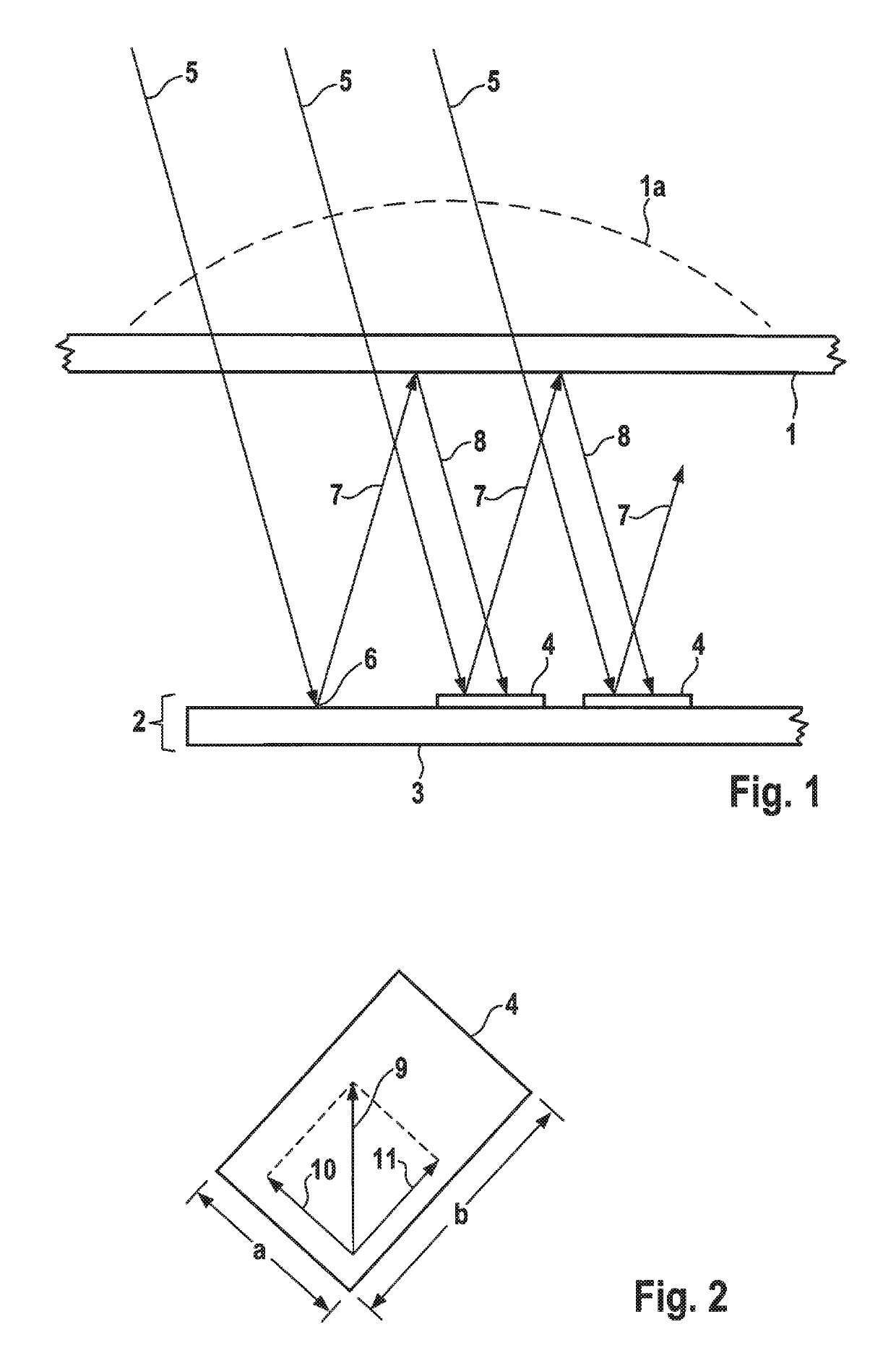
[0024]FIG. 1 schematically shows main components of a receiving device. For instance, a receiving antenna structure 2 having a circuit board 3 is shown, to which a receiving antenna is applied, whereby the receiving antenna 2, as shown, may be configured as a patch antenna by small metal surfaces on the top side of circuit board 3. Such patch antennas are widely used for transmitting and / or receiving microwave radiation or millimeter wave radiation and are easy to produce. This circuit board is protected from its surroundings by a housing part 1, which protects circuit board 3 from the effects of weather, dust and dirt and ensures long-term functional capability. Such a housing part is often referred to as a radome 1, which has been made, for example, of a material that is transparent to electromagnetic waves. In the automobile sector, such microwave or millimeter wave sensors are often situated behind body components in a manner that is invisible to other road users, so that it may...


PUM


Abstract

A device including a receiving antenna on a circuit board and a radome, multiple reflections of the received signals between the radome and the receiving antenna being avoided by using a polarization-rotating structure on the circuit board. The device may in particular be an integral part of a distance controller for adaptive cruise control of a motor vehicle.

Description

CROSS REFERENCE[0001]The present application claims the benefit under 35 U.S.C. § 119 of German Patent Application No. DE 102015225578.6 filed on Dec. 17, 2015, which is expressly incorporated herein by reference in its entirety.FIELD[0002]The present invention relates to a device which includes a receiving antenna on a circuit board and a radome, multiple reflections of the received signals between the radome and the receiving antenna being avoided by using a polarization-rotating structure on the circuit board. The device may in particular be an integral part of a distance controller for adaptive cruise control of a motor vehicle.BACKGROUND INFORMATION[0003]The paper “Millimeter-Wave Folded Reflector Antennas with High Gain, Low Loss, and Low Profile” by Wolfgang Menzel, Dietmar Pilz and Maysoun Al-Tikriti, June 2002 in the IEEE Antennas and Propagation Magazine, Vol. 44, No. 3, pages 24-28, describes applying reflective metal structures to a circuit board in order to construct a ...

Claims


Application Information

Patent Timeline
Patent Type & Authority Patents(United States)
IPC IPC(8): H01Q1/32H01Q1/38H01Q21/24H01Q15/02H01Q1/42H01Q1/36H01Q15/08H01Q21/08H01Q15/24
CPCH01Q1/3283H01Q1/36H01Q1/38H01Q1/42H01Q21/245H01Q15/08H01Q15/24H01Q21/08H01Q15/02H01Q1/3208H01Q15/14H01Q19/10H01Q21/065
Inventor MEYER, JOHANNESSTEINHAUER, MATTHIAS
Owner ROBERT BOSCH GMBH
Why Eureka
Try Eureka