Hydraulic positioner for large and heavy work pieces

Active Publication Date: 2019-05-07
ALM POSITIONERS INC
View PDF9 Cites 3 Cited by
  • Summary
  • Abstract
  • Description
  • Claims
  • Application Information

AI Technical Summary

Benefits of technology

The patent describes a new and improved hydraulic and control system for positioning fixture workpieces in robotic welding applications. The system includes a headstock and tailstock that can be independently moved along columns and have hydraulic cylinders to position them accurately. The system also includes non-contact absolute linear or rotary encoder position features for each axis, which improve programmed position repeatability. The system is failsafe to prevent collisions with the welded parts and reduces robot sensor search time, thereby increasing productivity and lowering costs. The need for more precise positioning is now being met with the improved hydraulic positioners, which offer better repeatability and cost-effectiveness.

Problems solved by technology

This variability of the repeatability range is undesirable for automated procedures, such as robotic welding.
Although these types of positioners are lower cost than traditional servo robotic positioners programmed point position variability limits their use for robotic manufacturing applications.
However, the choice of only a high or low flow rate can produce a halting, stepping motion.
In addition, over time, the string potentiometer used for position information can lose tension and become constricted due to the manufacturing environment conditions which may undermine position precision.
Hydraulic positioners typically are not used for such robotic welding applications since these positioners do not return accurately to programmed positions.
The ability of the positioner to return to the preprogrammed point position is called “repeatability.” In addition because of precision repeatability, the servo / gearbox positioners are very expensive.
This high cost of positioners can make financial justification difficult, thereby reducing automation opportunity & cost savings for industries that manufacture large, heavy workpieces.
While the servo motor / gearbox positioning machines have very good programmed position repeatability, the cost of these machines far exceeds the precision needed for GMAW welding operations, where the weld joint variability is much greater than the servo motor / gearbox repeatability.
However, despite the lower cost, hydraulic positioners generally are not used for robotic welding due to the poor repeatability for the programmed positions.
This inaccurate repeatability enhances the chance of robotic collision with the part or fixture as a robot approaches or departs from a weld location.
It can also compromise optimal specified weld position requirements undermining weld quality.
This repeatability deficiency discourages the use of hydraulic positioners for robotic welding.
While improved sensors may help robots find the weld joints, poor hydraulic positioner repeatability increases sensor search time, robot collision risk and diminishes weld quality.
Since conventional hydraulic positioners for large and heavy do not have sufficient accuracy and repeatability, this equipment is seldom used for highly precise, automated procedures, such as robotic welding.

Method used


Image

  • Hydraulic positioner for large and heavy work pieces
  • Hydraulic positioner for large and heavy work pieces
  • Hydraulic positioner for large and heavy work pieces

Examples


Embodiment Construction

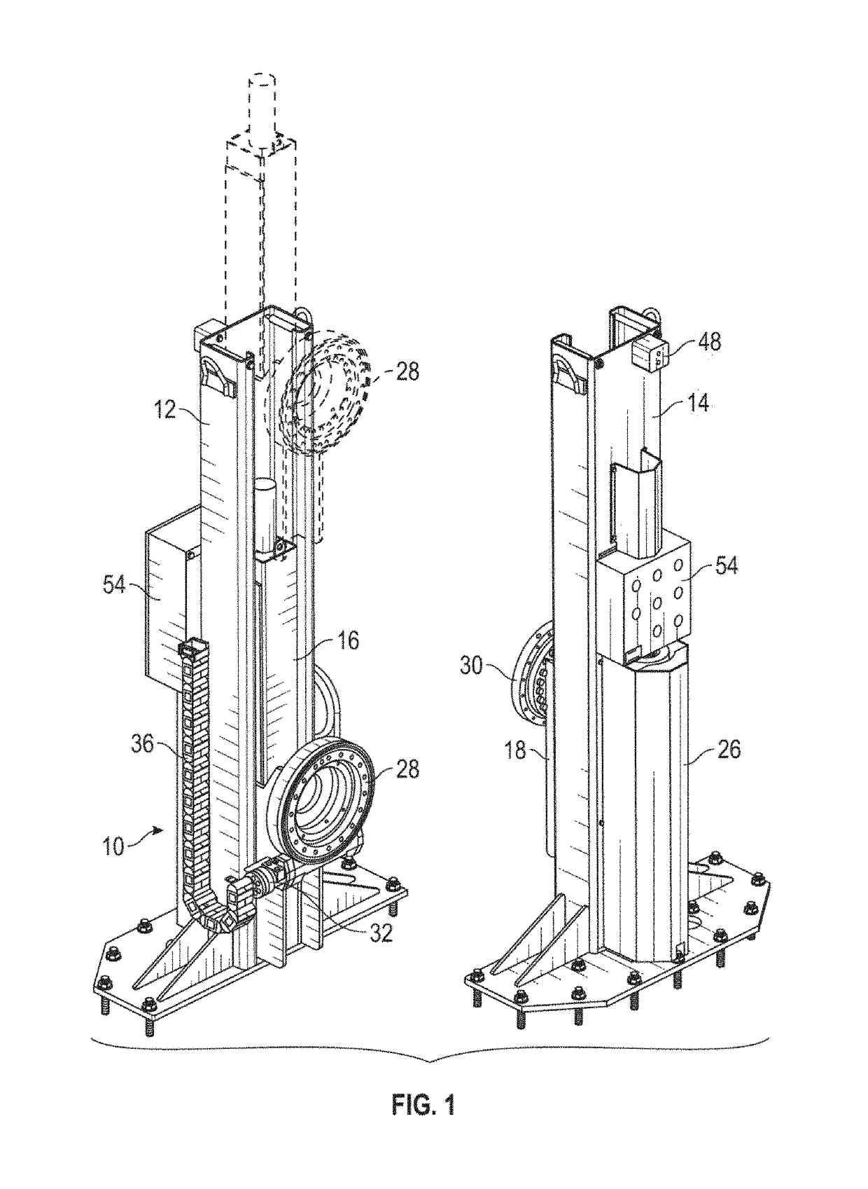
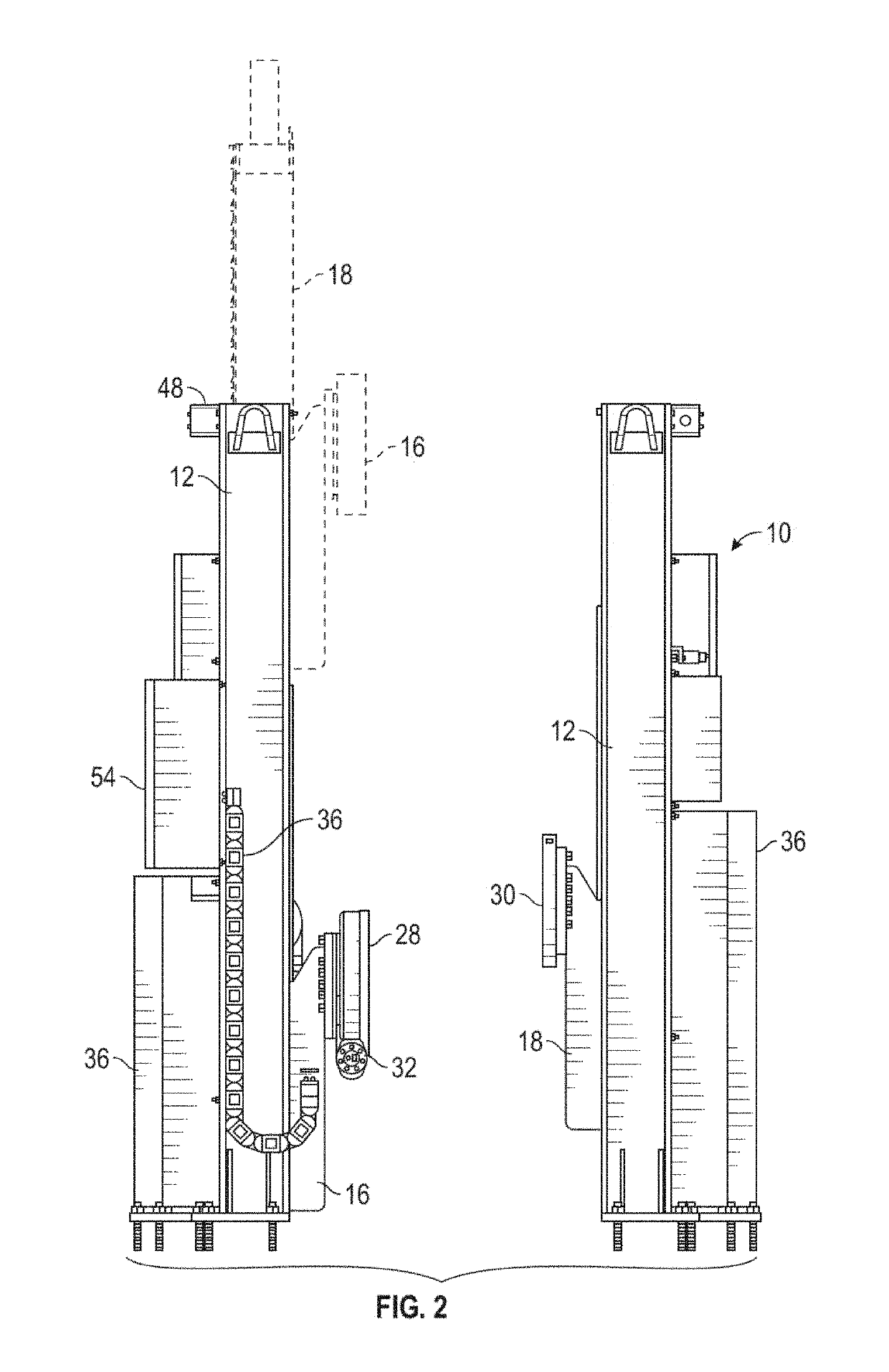
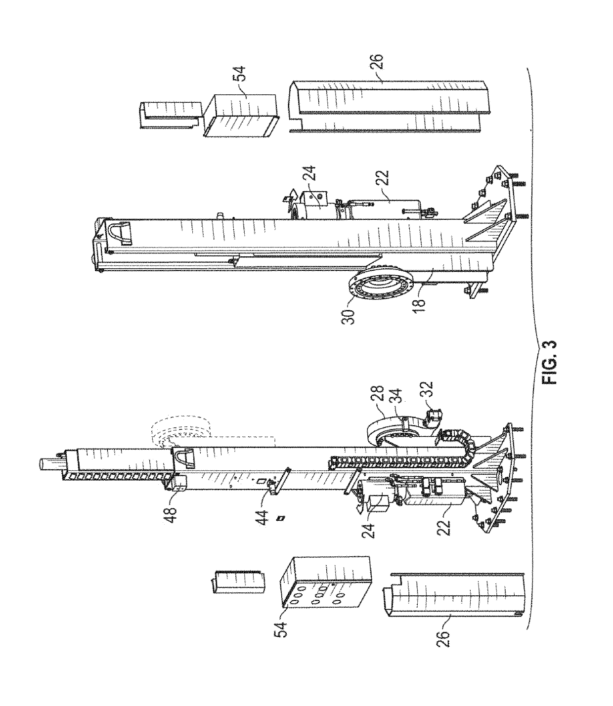
[0036]The hydraulic positioner of the present invention is generally designated by the reference numeral 10 in the drawings. The positioner 10 includes a headstock column 12 and a tailstock column 14 which are spaced apart so as to receive a workpiece (not shown) between the columns. The headstock column 12 includes a headstock carriage 16, and the tailstock column 14 includes a tailstock carriage 18. Each carriage 16, 18 can be raised and lowered by a hydraulic cylinder 20 mounted within the respective column 12, 14. A fluid reservoir 22 and a hydraulic motor pump 24 is provided on each column 12, 14 for moving the carriages 16, 18. A cover 26 detachably mounts to each column 12, 14 so as to enclose the reservoir 22 and pump 24.

[0037]A headstock 28 is rotatably mounted on the headstock carriage 16, and a tailstock 30 is rotatably mounted on the tailstock carriage 18. A hydraulic motor 32 is provided for each of the headstock 28 and tailstock 30 for rotation in clockwise and counter...


PUM


Abstract

A heavy duty hydraulic positioner has headstock and tailstock carriages to support large and heavy work pieces to be processed in a manufacturing operation, such as robotic welding. Each carriage is independently movable along a column, and has a hard stop associated with each pre-program workpiece position, thereby providing accurate repeatability. Repeatability is further enhanced by linear, noncontact absolute encoders for the elevation axes of the headstock and tailstock, and rotary, noncontact absolute encoders for the rotary axes of the headstock and tailstock.

Description

BACKGROUND OF THE INVENTION[0001]Hydraulic positioners having a high weight capacity are well known for manufacturing operations, such as manual welding and manual assembly. For example, applicant's prior art positioners can elevate and rotate the workpiece at either the head or tail end, or both, with programmed work points having repeatability within + / −0.250 inch for each axis, thereby leading to a maximum repeatability variation of + / −0.750 inch relative to the programmed work point for the elevating headstock and tailstock with a rotary axis. This variability of the repeatability range is undesirable for automated procedures, such as robotic welding. Although these types of positioners are lower cost than traditional servo robotic positioners programmed point position variability limits their use for robotic manufacturing applications.[0002]Applicant's prior art positioner utilizes a single acting hydraulic cylinder for each of the headstock and tailstock carriages. Starting fr...

Claims


Application Information

Patent Timeline
IPC IPC(8): B66F11/00B66F7/08B66C13/18B66F9/18B66C1/42
CPCB66F7/08B66F9/18B66C13/18B66C1/427
Inventor GRUNNET, DOUGLASBRUNENN, COLTEN JAYDONETH, ROBERT BRIANHILL, JACOB EVAN
Owner ALM POSITIONERS INC
Why Eureka
Try Eureka