System and process for recovering power and steam from regenerator flue gas

Active Publication Date: 2015-09-10
UOP LLC
View PDF26 Cites 0 Cited by
  • Summary
  • Abstract
  • Description
  • Claims
  • Application Information

AI Technical Summary

Benefits of technology

This patent is about a process for generating power in a processing unit. The process involves using a regenerator to produce a flue gas stream, which is then routed to a steam generator. The flue gas stream is then treated to remove catalyst particles. The cleaned gas is then routed to a combustor / expander unit, where it is used to rotate a turbine and generate power. This process can lead to increased power recovery and steam generation, improving the overall efficiency and economics of the processing unit. The combustor / expander unit may be standardized for improved cost-effectiveness.

Problems solved by technology

As mentioned above, traditional FCC power recovery technologies are limited with regard to the amount of power recovery because the turbine inlet temperature is constrained by the maximum temperature allowed by the regenerator.

Method used


Image

  • System and process for recovering power and steam from regenerator flue gas
  • System and process for recovering power and steam from regenerator flue gas
  • System and process for recovering power and steam from regenerator flue gas

Examples


Embodiment Construction

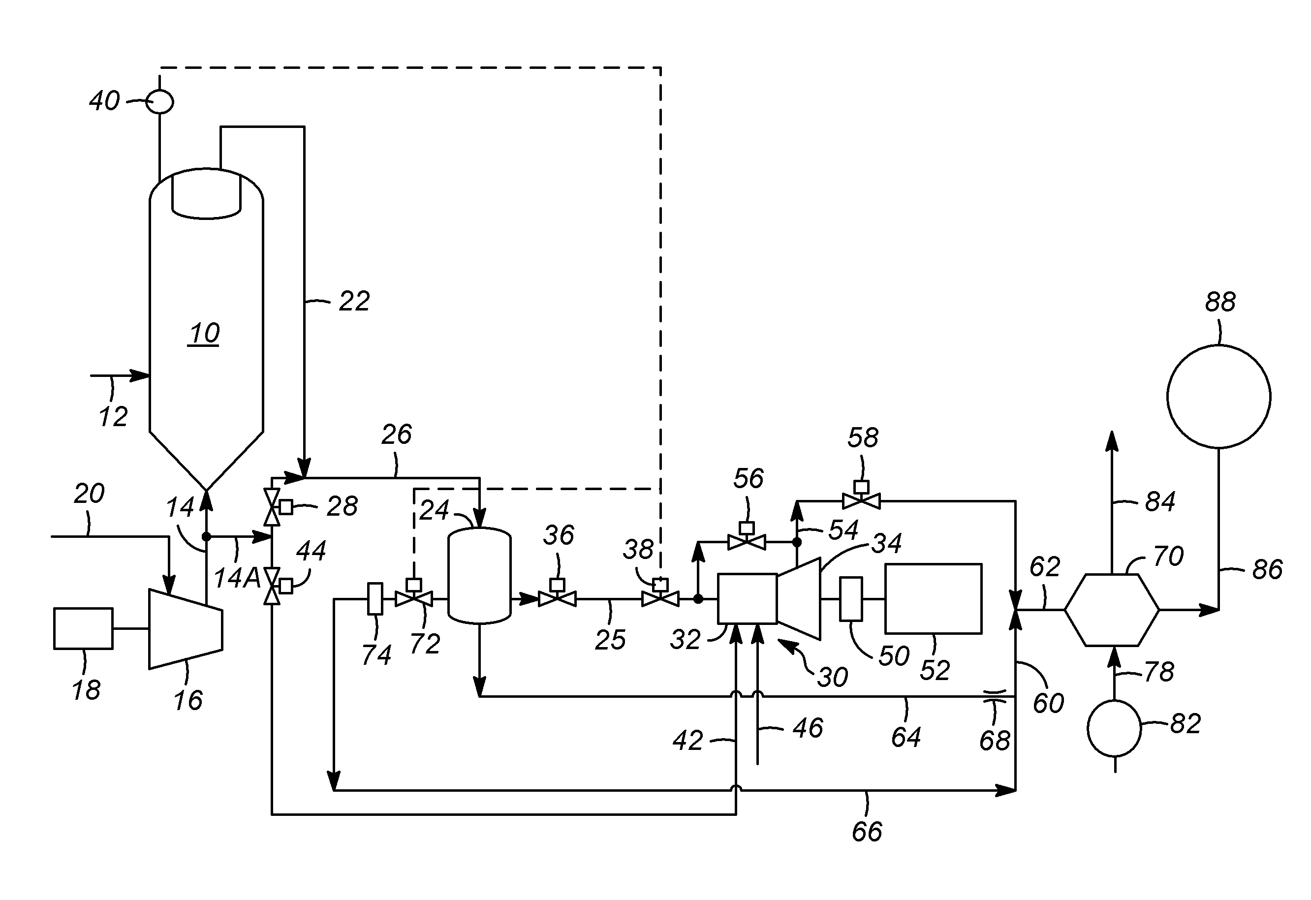
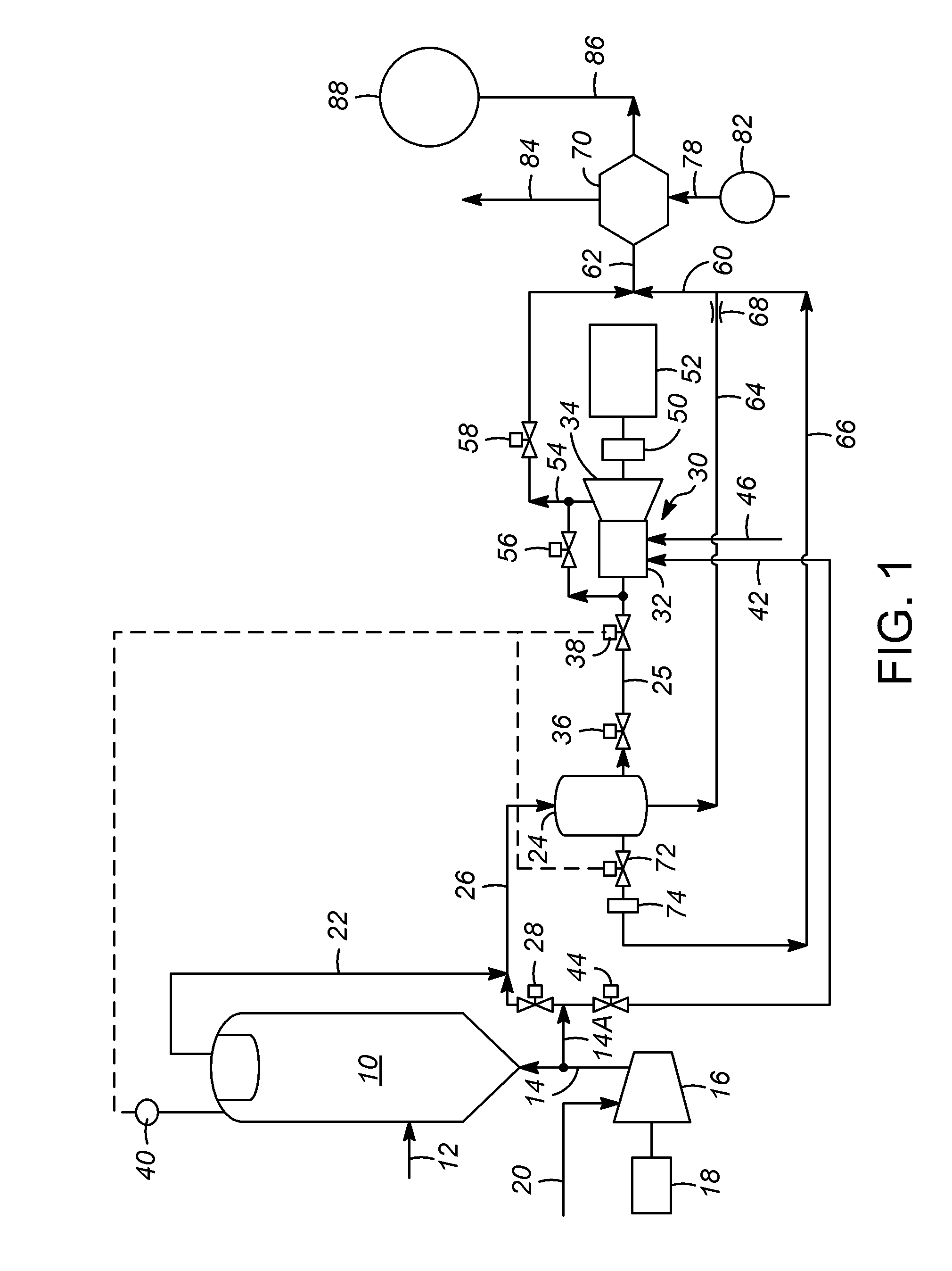
[0012]FIG. 1 is the process flow diagram of one example of an embodiment of the present process for generating power in a processing unit. Although this example is an FCC unit, the present power generation process of this embodiment, and other embodiments described herein, can be used in other types of processing units, such as such as in methanol to olefins (MTO) processing units and in biomass conversion processing units.

[0013]In this example of the process, a regenerator 10, which is used to oxidize coke from a catalyst, receives a catalyst stream 12 from a reactor (such as an FCC reactor that cracks a hydrocarbon feed into simpler molecules through contact with a catalyst). The regenerator 10 also receives a stream 14 of air which has passed through a blower 16 powered by a motor 18. The blower 16 is fed by a filtered air stream 20.

[0014]Flue gas stream 22 exits the regenerator, and is routed to a filtering unit 24. The input stream to the filtering unit 24 is preferably a combi...


PUM


Abstract

A power generation process for use in a processing unit that includes the steps of: using a regenerator to produce a flue gas stream; removing catalyst particles from the flue gas stream; routing the flue gas stream to a combustor / expander unit after performing the step of removing catalyst particles; and using rotation of the turbine of the combustor / expander unit as a source of rotary power. Preferably, the combustor / expander unit includes a combustion chamber and a power recovery turbine housed within a single casing. In certain embodiments, the flue gas stream is routed between the regenerator and the combustor / expander without passing through a compressor.

Description

[0001]The present invention relates generally to a power generation process for use in a processing unit, such as a fluid catalytic cracking (FCC) unit, and more particularly to a process for generating power from regenerator flue gas that includes a combustor / expander unit formed of a combustion chamber and a power recovery turbine housed within a single casing. Preferably, the process also includes components for recovering steam from the flue gas.BACKGROUND OF THE INVENTION[0002]Flue gas from the regenerator of a fluid catalytic cracking (FCC) unit can be used for steam generation in a Flue Gas Cooler (FGC). Alternatively, the flue gas can be used to make power in an expander, and then to generate steam in the FGC. Traditional FCC power recovery technologies are limited with regard to the amount of power recovery because the inlet temperature of the expander is constrained by the maximum temperature of the flue gas exiting the regenerator.BRIEF SUMMARY OF THE INVENTION[0003]In em...

Claims


Application Information

Patent Timeline
IPC IPC(8): F02C3/22
CPCF02C3/22F01K5/02F02C3/205Y02E50/10
Inventor ZHU, XIN X.ALVES, JOAO JORGE DA SILVA FERREIRAPALMAS, PAOLOJOHNSON II, RICHARD A.VAN DE COTTE, MICHAEL R.
Owner UOP LLC
Why Eureka
Try Eureka