Auto tensioner

a technology of auto tensioner and tensioner body, which is applied in the direction of belt/chain/gearing, mechanical equipment, belt/chain/gearing, etc., can solve the problems of belt wear or slippage sound, and achieve the effects of small frictional force, large damping force, and large frictional for

Active Publication Date: 2019-05-07
MITSUBOSHI BELTING LTD
View PDF53 Cites 0 Cited by
  • Summary
  • Abstract
  • Description
  • Claims
  • Application Information

AI Technical Summary

Benefits of technology

[0021]According to the first aspect of the present invention, in the case where belt tension increases, whereby the rotating member rotates against the biasing force of the coil spring, the arcuate surface of the friction member slides on the inner circumferential surface of the cylindrical part of the base and a frictional force is generated between the arcuate surface of the friction member and the inner circumferential surface of the cylindrical part of the base. The arcuate surface of the friction member is located further toward the opposite direction side to a rotational biasing direction (the one direction) of the coil spring, that is, the rotational direction side of the rotating member, than the first locking part of the friction member in the circumferential direction. For this reason, a force that the first locking part of the friction member received from the rotating member can be used as a force pressing the arcuate surface of the friction member against the inner circumferential surface of the cylindrical part of the base. Therefore, it is possible to generate a large frictional force between the arcuate surface of the friction member and the inner circumferential surface of the cylindrical part of the base, and thus it is possible to generate a large damping force sufficiently damping the oscillation of the rotating member.
[0022]Conversely, in the case where belt tension decreases, whereby the rotating member is rotated by the biasing force of the coil spring, the friction member receives a biasing force in the circumferential direction from the coil spring. However, the arcuate surface of the friction member is located further toward the opposite direction side to the rotational biasing direction of the coil spring than the first locking part of the friction member in the circumferential direction, and therefore, the arcuate surface of the friction member is not pressed against the inner circumferential surface of the cylindrical part of the base by the biasing force in the circumferential direction of the coil spring and an increase in the frictional force between the arcuate surface of the friction member and the inner circumferential surface of the cylindrical part of the base can be suppressed. Therefore, it is possible to generate a small frictional force between frictional force between the arcuate surface of the friction member and the inner circumferential surface of the cylindrical part of the base and it is possible to make the oscillation of the rotating member sufficiently follow the decrease in belt tension.
[0023]Further, the auto-tensioner according to the present invention realizes the above-described asymmetric damping characteristic by using only the friction member and the coil spring, and therefore, it is lightweight and has a small number of parts, and assembling thereof is easy. Furthermore, one end portion of the coil spring is locked to the friction member sandwiched in the radial direction between the cylindrical part of the base and the rotating member, and therefore, it is not necessary to secure a large space between the coil spring and the cylindrical part of the base, and thus the auto-tensioner can be downsized.
[0024]According to the second aspect of the present invention, the arcuate surface of the friction member is formed further toward the opposite direction side to the rotational biasing direction (the one direction) of the coil spring than the first locking part, and therefore, the second locking part is also formed further toward the opposite direction side to the rotational biasing direction of the coil spring than the first locking part, whereby the friction member can be downsized in the circumferential direction, as compared to a case where the first locking part is formed within the range in the circumferential direction of the second locking part.
[0025]According to the third aspect of the present invention, the first locking part and the second locking part are configured with the second part having a relatively high surface hardness, and therefore, even in the case where a force acting on the first locking part and the second locking part increases according to an increase in belt tension, damage to (deformation or depression of) the first locking part and the second locking part can be prevented. Furthermore, since damage to the first locking part and the second locking part is prevented, application on a high-load drive system in which large belt tension is required, or realization of such as downsizing of the friction member is also possible.
[0026]The first part configures the arcuate surface and a surface which continues to the arcuate surface and comes into contact with the rotating member in the axial direction in the friction member, and is made such that falling-off in the axial direction is prevented.

Problems solved by technology

A belt slip occurs due to such variation in belt tension, and thus a problem such as slip sound or belt wear occurs.

Method used


Image

  • Auto tensioner
  • Auto tensioner
  • Auto tensioner

Examples


first embodiment

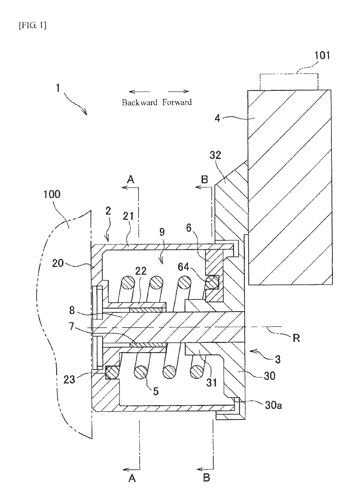
[0047]As illustrated in FIG. 1, an auto-tensioner 1 of the present invention is provided with a base 2 which is fixed to an engine block 100 illustrated by a two-dot chain line in FIG. 1, a rotating member 3 supported so as to be rotatable about an axis R with respect to the base 2, the pulley 4 rotatably provided at the rotating member 3, a coil spring 5, and a friction member 6. The leftward direction in FIG. 1 is defined as a backward direction and the rightward direction is defined as a forward direction. A radial direction centered on the axis R is defined simply as a radial direction and a circumferential direction around the axis R is defined simply as a circumferential direction.

[0048]The base 2 is, for example, a metal part made of an aluminum alloy casting or the like, and is provided with an annular pedestal part 20 which is fixed to the engine block 100, an outer cylindrical part (cylindrical part) 21 extending forward from an outer edge portion of the pedestal part 20, ...

third embodiment

[0060]The friction member 6 is formed of a material having high lubricity, which is obtained by compounding fibers, a filler, a solid lubricant, or the like with synthetic resin. As the synthetic resin configuring the friction member 6, for example, thermoplastic resin such as polyamide, polyacetal, polytetrafluoroethylene, polyphenylene sulfide, or ultra-high molecular weight polyethylene, or thermosetting resin such as phenol can be used. As long as the front face and an arcuate surface 60, which is described later, are configured with the above-described material, the friction member 6 may include a material other than the above-described material (refer to, e.g., a third embodiment).

[0061]The friction member 6 has a substantially fan-shaped cross-sectional shape orthogonal to the axis R and has the arcuate surface 60, a locking surface 61 opposed to the arcuate surface 60, and two side surfaces 62 and 63 opposed to each other in the circumferential direction. The arcuate surface...

fourth embodiment

[0086] since one end of the coil spring 405 does not have a linear portion, the length of the coil spring 405 can be shortened, and therefore, the size of the retention groove (the second locking part) 464 can be reduced, whereby the friction member 6 can be downsized in the circumferential direction (e.g., a portion S illustrated by hatching in FIG. 10 can be omitted). A further reduction in the weight of the auto-tensioner 1 can be realized by the shortening of the length of the coil spring 405 and the downsizing in the circumferential direction of the friction member 6. In addition, since working such as bending one end of the coil spring 405 is not required, simplification of a manufacturing process and a reduction in manufacturing cost can be realized.

[0087]Subsequently, the auto-tensioner 1 of a fifth embodiment of the present invention will be described with reference to FIG. 11. In the first embodiment described above, the front end portion (one end) of the coil spring 5 is ...


PUM


Abstract

The present invention relates to an auto-tensioner containing a base having a cylindrical part, a rotating member supported rotatably to the base, a pulley provided at the rotating member, a friction member sandwiched between the cylindrical part and the rotating member, and a coil spring locked to the friction member and the base and disposed in a state of being compressed in an axial direction, thereby biasing the rotating member in one direction, in which the friction member has an arcuate surface capable of sliding along the cylindrical part, a first locking part located further toward the one direction side than the arcuate surface in a circumferential direction of the cylindrical part and locked to the rotating member, and a second locking part locked to one end of the coil spring.

Description

CROSS REFERENCE TO RELATED APPLICATIONS:[0001]This is a U.S. National Phase Application under 35 U.S.C. § 371 of International Application No. PCT / JP2015 / 053871, filed Feb. 12, 2015, which claims priority to Japanese Application Nos. 2014-028133, 2014-262127 and 2015-010210 filed Feb. 18, 2014, Dec. 25, 2014, and Jan. 22, 2015, respectively, and which was published Under PCT Article 21(2), the entire contents of which are incorporated herein by reference.TECHNICAL FIELD[0002]The present invention relates to an auto-tensioner for automatically maintaining tension of a belt appropriately.BACKGROUND ART[0003]For example, in a belt for auxiliary machine drive of an automobile engine, belt tension varies due to rotation fluctuation caused by engine combustion. A belt slip occurs due to such variation in belt tension, and thus a problem such as slip sound or belt wear occurs. In order to solve this, conventionally, an auto-tensioner has been adopted as a mechanism to suppress the occurren...

Claims


Application Information

Patent Timeline
Patent Type & Authority Patents(United States)
IPC IPC(8): F16H7/08F16H7/12
CPCF16H7/1218F16H7/0829F16H7/12F16H2007/0893F16H2007/081F16H2007/084
Inventor OISHI, SATOSHINISHIYAMA, KOJIYONEDA, TETSUO
Owner MITSUBOSHI BELTING LTD
Why Eureka
Try Eureka