Graphical user interface for medical instruments

a technology of medical instruments and user interfaces, applied in the field of graphical user interfaces, can solve problems such as unwanted side effects and hamper the effectiveness of therapy devices, and achieve the effect of high resolution

Active Publication Date: 2019-05-07
KONINKLJIJKE PHILIPS NV
View PDF5 Cites 7 Cited by
  • Summary
  • Abstract
  • Description
  • Claims
  • Application Information

AI Technical Summary

Benefits of technology

[0033]This embodiment may be beneficial because providing the data as described above rendered on a graphical user interface and providing a graphical user interface that is operable for receiving a halt command, the cognitive burden of a user manually stopping or pausing the operation of a treatment system is greatly reduced.
[0035]This embodiment may be beneficial because the use of the interpolated image data determined by the displayed plane position may provide a view to the user which further reduces the cognitive burden of deciding or operating the user interface to halt the sonication or heating.
[0037]In another embodiment, the template display planes are linear accelerator beam views, that is, planes that are centered on the target zone and oriented at fixed gantry angles to cover the target from various directions, and the template parameter is the target zone registration. As a result, if the target zone moves and planes are re-rendered, the beam views are seen centered on the target zone. This embodiment may be beneficial because moving the beam views with the target zone reduces the cognitive burden as the user is not forced to mentally stabilize the flickering images as the target moves in and out of the display planes.
[0038]In another embodiment the template plane is operable for displaying a distance between the reference location and the at least one of the one or more anatomical references. This embodiment may be beneficial because providing a number may further make the cognitive burden of operating the graphical user interface reduced.
[0045]In another embodiment execution of the instructions further causes the processor to render the one or more anatomical references such that the position of the one or more anatomical references is displayed for at least an entire period of the cyclical motion of the subject. This may be extremely beneficial because as the energy is deposited into the treatment zone portions of the subject may move cyclically. By illustrating the anatomical references for an entire period the operator may better gauge if the region indicated by the anatomical reference will move or interfere with the treatment zone.

Problems solved by technology

Tissue movement, e.g., due to respiratory or peristaltic motion, creates unwanted side effects and hampers the effectiveness of a therapy device not linked to the movement.

Method used


Image

  • Graphical user interface for medical instruments
  • Graphical user interface for medical instruments
  • Graphical user interface for medical instruments

Examples


Embodiment Construction

[0081]Like numbered elements in these figures are either equivalent elements or perform the same function. Elements which have been discussed previously will not necessarily be discussed in later figures if the function is equivalent.

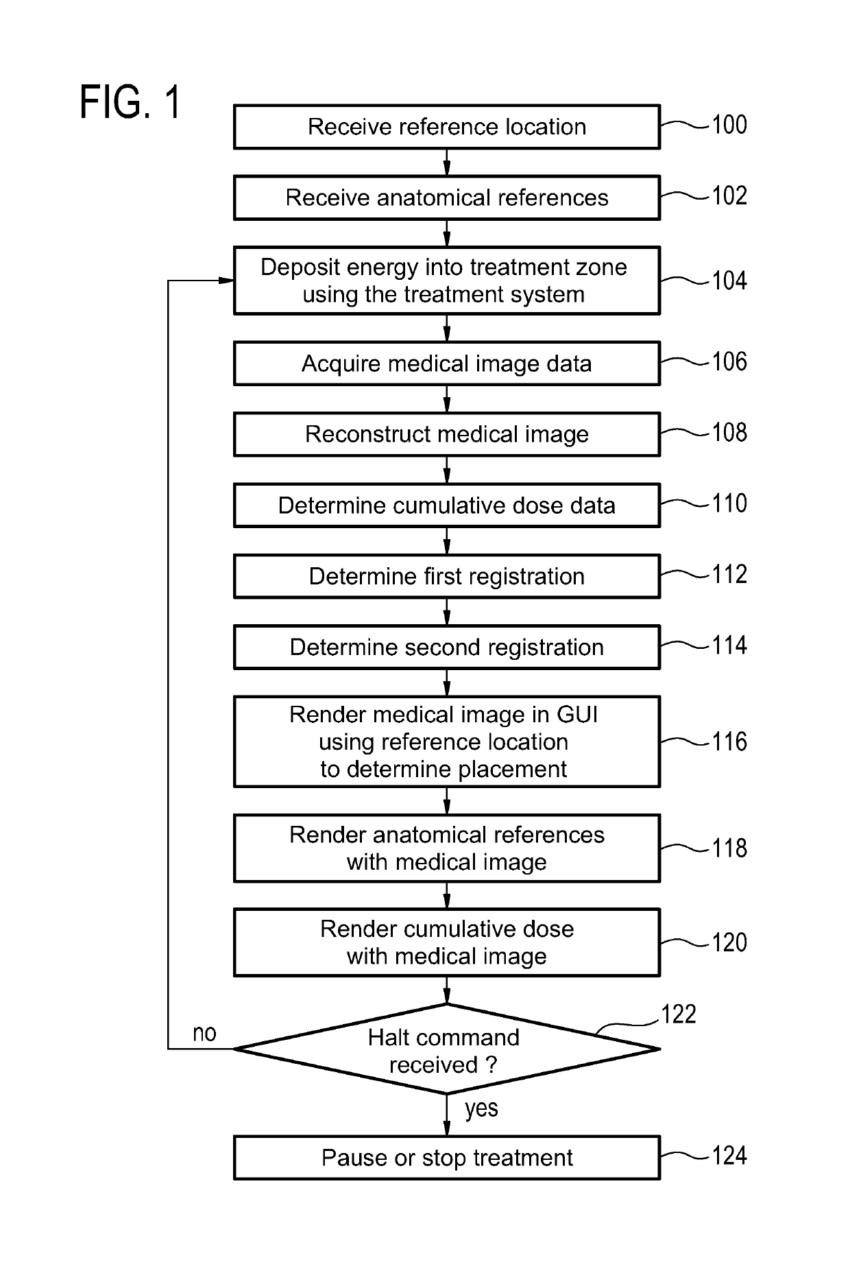
[0082]FIG. 1 shows a flow diagram which illustrates a method according to an embodiment of the invention. First in step 100 a reference location is received. This may for instance be received from a graphical user interface or it may be data which is received from a memory or from another computer system. Likewise in step 102, anatomical references are received. The anatomical references may also be received in the same way that the reference location was received. In some embodiments the reference location and the anatomical references will be received within part of a treatment plan. Next in step 104 energy is deposited into a treatment zone using the treatment system. Next in step 106 medical image data is acquired. Steps 104 and 106 may be performed...


PUM


Abstract

The invention provides for medical instrument (200, 300) comprising a medical imaging system (202, 302) for acquiring medical image data (236) from an imaging zone (204) and a treatment system (206, 322) for depositing energy into a treatment zone (208). A processor executing instructions receives (100) a selection of a reference location and one or more anatomical references. The instructions cause the processor to repeatedly: deposit energy into the subject using a treatment system; acquire medical imaging data with the medical imaging system; determine a cumulative dosage data from the medical image data; determine (112) a first registration (242) for the reference location; determine (114) a second registration (244) for the one or more anatomical references; render (116) the medical image, the one or more anatomical references, and the cumulative dosage data (270) in the graphical user interface; and halt the deposition of energy into the subject if a halt command is received from the graphical user interface.

Description

CROSS-REFERENCE TO PRIOR APPLICATIONS[0001]This application is the U.S. National Phase application under 35 U.S.C. § 371 of International Application No. PCT / IB2013 / 054506, filed on May 31, 2013, which claims the benefit of U.S. Provisional Patent Application No. 61 / 661,842, filed on Jun. 20, 2012 and European Patent Application No. 12181954.4, filed on Aug. 28, 2012. These applications are hereby incorporated by reference herein.TECHNICAL FIELD[0002]The invention relates to graphical user interfaces for controlling medical instruments, in particular to displaying medical images on a display for reducing the cognitive burden for stopping or pausing a treatment.BACKGROUND OF THE INVENTION[0003]Tissue movement, e.g., due to respiratory or peristaltic motion, creates unwanted side effects and hampers the effectiveness of a therapy device not linked to the movement. Such devices are, for example, a linear accelerator and a high intensity focused ultrasound transducer. Automated motion c...

Claims


Application Information

Patent Timeline
Patent Type & Authority Patents(United States)
IPC IPC(8): A61B18/12A61B18/18A61B18/20A61N5/10G16H40/63A61B5/01A61B8/00A61B5/00A61B5/055A61B8/13A61N7/00A61N5/00A61F7/00G06F3/0484A61N7/02G01R33/48G01R33/54A61B34/00A61B18/00A61B90/00
CPCG06F3/0484A61B5/055A61B5/7435A61B8/13A61B8/465A61B18/12A61B18/1815A61B18/20A61B34/25A61F7/00A61N5/00A61N5/1084A61N7/00A61N7/02G01R33/4808G01R33/546G16H40/63A61B5/015G01R33/4814A61B2018/00577A61B2034/254A61B2090/374F04C2270/041
Inventor VAHALA, ERKKI TAPANIYLIHAUTALA, MIKA PETRIKOTYS, MELANIE SUZANNE
Owner KONINKLJIJKE PHILIPS NV
Why Eureka
Try Eureka