Velocity selective thermal atomic beam inertial sensor

Active Publication Date: 2019-05-14
AOSENSE
View PDF6 Cites 8 Cited by
  • Summary
  • Abstract
  • Description
  • Claims
  • Application Information

AI Technical Summary

Problems solved by technology

There are significant challenges of using atomic interferometers in a dynamic environment, such as in a spacecraft or airplane, where vibrations and accelerations can be large.

Method used


Image

  • Velocity selective thermal atomic beam inertial sensor
  • Velocity selective thermal atomic beam inertial sensor
  • Velocity selective thermal atomic beam inertial sensor

Examples


Embodiment Construction

[0015]The invention can be implemented in numerous ways, including as a process; an apparatus; a system; a composition of matter; a computer program product embodied on a computer readable storage medium; and / or a processor, such as a processor configured to execute instructions stored on and / or provided by a memory coupled to the processor. In this specification, these implementations, or any other form that the invention may take, may be referred to as techniques. In general, the order of the steps of disclosed processes may be altered within the scope of the invention. Unless stated otherwise, a component such as a processor or a memory described as being configured to perform a task may be implemented as a general component that is temporarily configured to perform the task at a given time or a specific component that is manufactured to perform the task. As used herein, the term ‘processor’ refers to one or more devices, circuits, and / or processing cores configured to process da...


PUM


Abstract

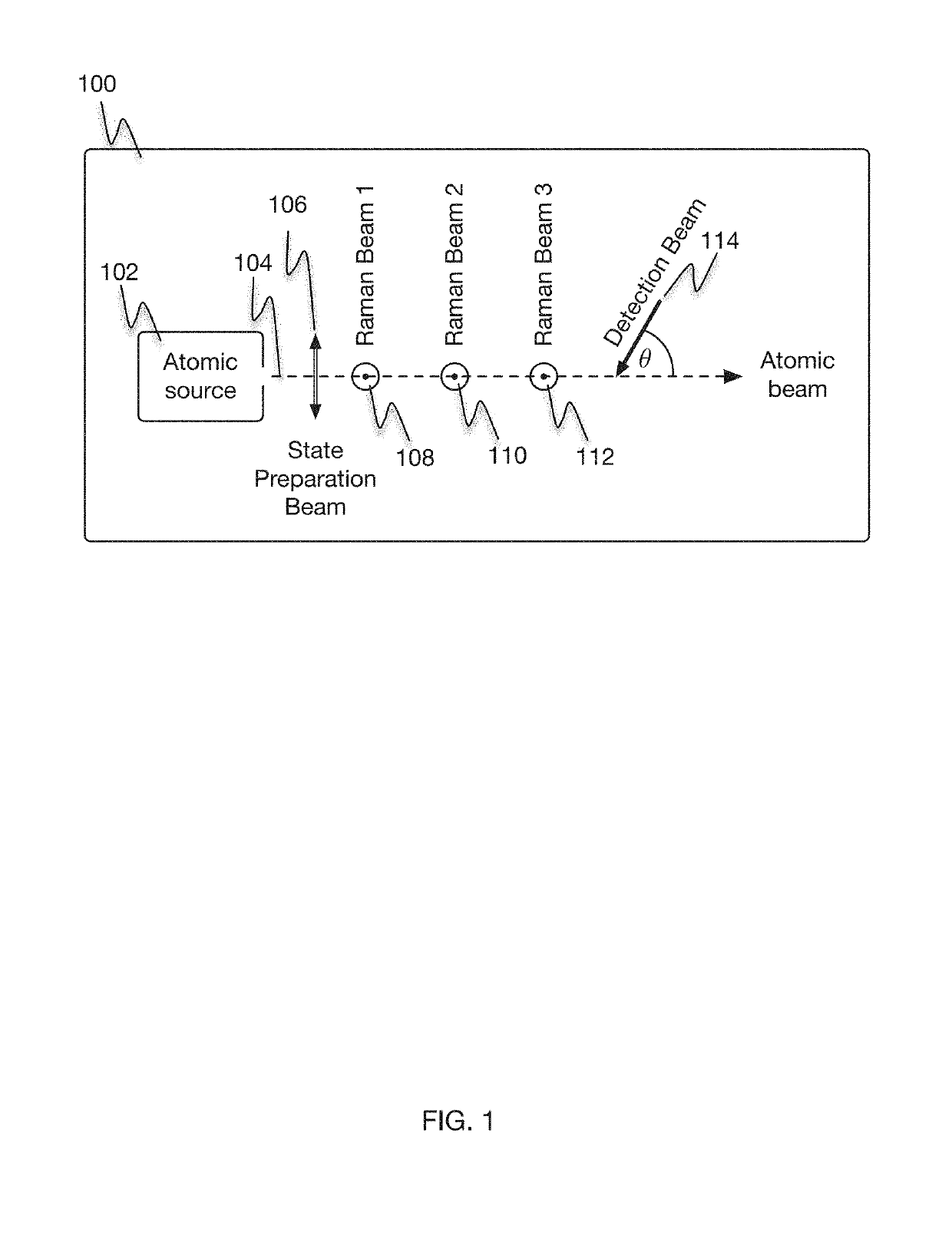
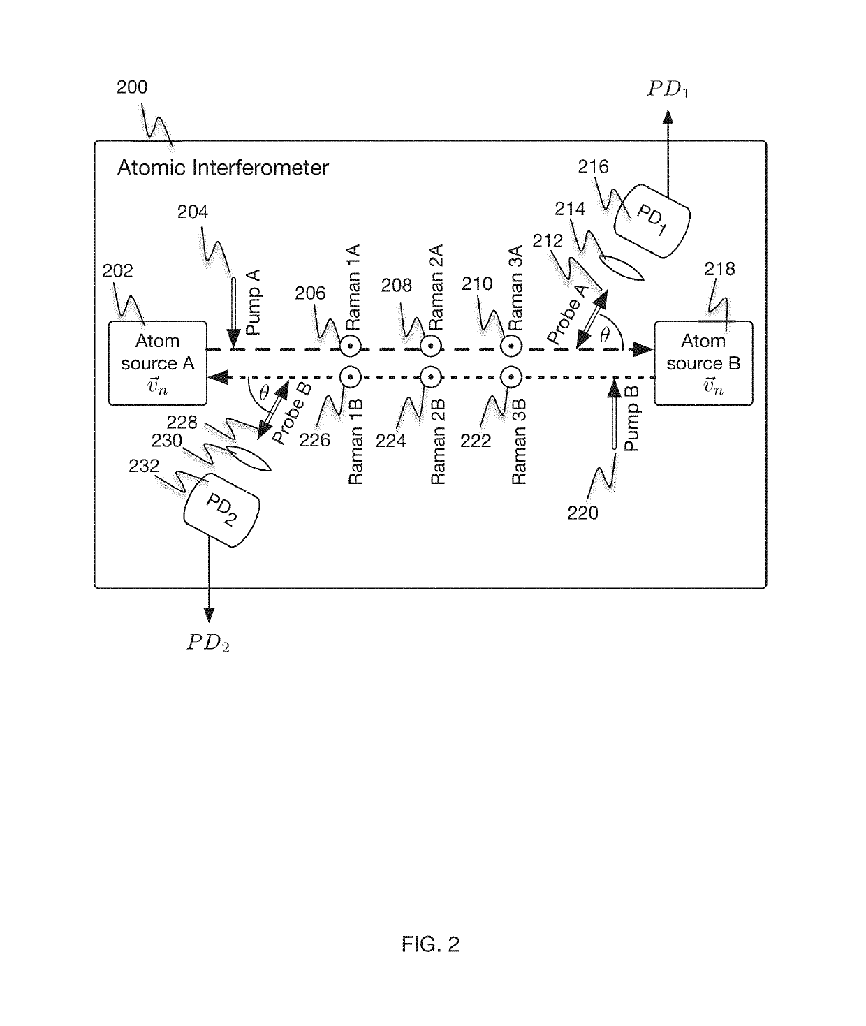
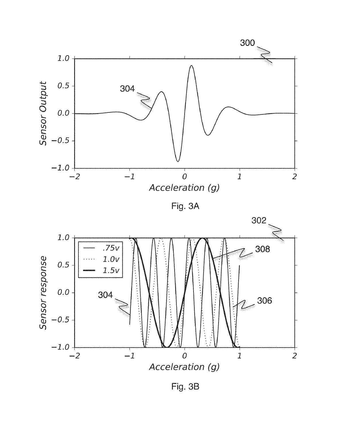
An atom interferometer device for inertial sensing includes one or more thermal atomic sources, a state preparation laser, a set of lasers, and a detection laser. The one or more thermal atomic sources provide one or more atomic beams. A state preparation laser is disposed to provide a state preparation laser beam nominally perpendicular to each of the one or more atomic beams. A set of lasers is disposed to provide interrogation laser beams that interrogate the one or more atomic beams to assist in generating atom interference. A detection laser is disposed to provide a detection laser beam, which is angled at a first angle to the each of the one or more atomic beams in order to enhance the dynamic range of the device by enabling velocity selectivity of atoms used in detecting the atom interference.

Description

[0001]This invention was made with government support under contract #FA9453-17-C-0470 awarded by AFRL and #N00014-15-C-5022 awarded by ONR. The government has certain rights in the invention.BACKGROUND OF THE INVENTION[0002]Matter exhibits wave-like properties similar to light; atomic interferometry has become an indispensable tool for precision measurements because the typical de Broglie wavelengths associated with massive particles are very small compared to wavelengths associated with massless photons of visible light. These wave-like properties of matter allow interference measurements to be exploited at a scale orders of magnitude smaller than for light. Examples of these precision measurements include high precision inertial sensing and gravity gradiometry to measurements of fundamental physical constants and quantum phenomena. Typically, these precision measurements take place in static environments such as in a research laboratory. There are significant challenges of using ...

Claims


Application Information

Patent Timeline
Patent Type & Authority Patents(United States)
IPC IPC(8): G01C19/58G21K1/00
CPCG21K1/006G01C19/58G01P15/093G21K1/00
Inventor CINGOZ, ARMANZHU, MIAOSHVERDIN, MIROSLAV Y.CASHEN, MATTHEW
Owner AOSENSE
Why Eureka
Try Eureka