Ion beam assisted deposition system

An ion beam assisted deposition system technology, applied in the field of ion beam assisted deposition devices, can solve the problems of reduced film quality, shortened service life of heaters, inability to adjust individually, etc., and achieves the effect of compact structure

Pending Publication Date: 2017-12-15
JINHUA VOCATIONAL TECH COLLEGE
View PDF1 Cites 8 Cited by
  • Summary
  • Abstract
  • Description
  • Claims
  • Application Information

AI Technical Summary

Problems solved by technology

Ion source is the core component of ion beam assisted deposition, but existing wide-beam ion source has the defective of following technology: (1) the ion beam emitted by some active gas such as hydrogen as source gas wide-beam ion source usually contains polyatomic a mixture of hydrogen ions and monatomic hydrogen ions, H 2 + , H + , their ratio can only be adjusted within a narrow range without changing other beam parameters; (2) Each ion species of molecules and atoms has an independent energy distribution, which cannot be adjusted individually. In the ion beam colliding with the surface of the film, various components overlap each other, resulting in the broadening of the energy distribution, which reduces the control accuracy of the film growth process and leads to a decline in the quality of the film; (3) based on magnetic field or based on The electrostatic ion mass filtering method will lead to the loss of ion beam current, especially in the case of lower ion energy. In addition, the heater is usually wound into a helical configuration by a heating wire. In the existing technical solution, the heating The wire does not have good thermal conductivity at the end, which leads to local overheating during the working process and reduces the service life of the heater. The ion beam assisted deposition system can solve the above problems

Method used


Image

  • Ion beam assisted deposition system
  • Ion beam assisted deposition system

Examples


Embodiment Construction

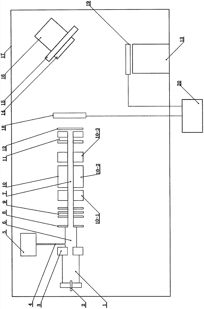
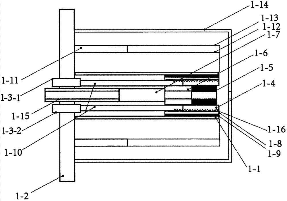
[0030] Such as figure 1 Is a schematic diagram of the structure of the present invention, such as figure 2 It is a schematic diagram of the enlarged structure of a hollow cathode, which mainly includes an ion beam source composed of a hollow cathode (1), a trigger module (2), an anode (3), a gas pipe (4), a gas tank (5), and a plasma chamber (6) , Drift tube (7), extraction electrode (8), electrode group I (9), three groups of independent quadrupole group I (10-1), quadrupole group II (10-2), quadruple rod The quadruple rod (10) composed of group III (10-3), electrode group II (11), stainless steel grid (12), electron beam evaporation source (13), sample (14), sample stage (15), displacement Table (16), vacuum chamber (17), baffle I (18), baffle II (19), control unit (20) and cables, the hollow cathode (1) includes graphite cathode tube (1-1), Stainless steel base (1-2), electrode I (1-3-1), electrode II (1-3-2), boron nitride heating tube (1-4), launch tube (1-5), graphite ...


PUM


Abstract

The invention relates to the technical field of film material preparation, and discloses an ion beam assisted deposition system. A plasma cathode electron gun based on pseudo spark discharge is adopted as the ion beam assisted deposition system; unlike a typical ion beam assisted deposition device, the plasma cathode electron gun has multiple electrode gaps, and therefore electron beams for the hollow cathode ionization process and the subsequent conduction ionization process can be effectively generated; the energy and the beam current density of the electron beams of a hollow cathode phase are controller through different breakdown methods, the iron mass resolution is high enough, and therefore ions of hydrogen atoms and ions of hydrogen molecules can be separated; the ion energy is low and ranges from several eV to several hundred eV; the ion beam current is high enough, and therefore it is guaranteed that the ion beam assisted deposition process can be conducted; the ion beam current is wide, the diameter of the beam current is 10 mm, the hydrogen ion current density is 1 microampere per square centimeter, and therefore a deposition experiment can be conducted on a large-area substrate; mass selection on the ions only depends on an electric field and does not depend on a magnetic field, the structure is compact, and therefore the atomic beam current or active gas molecule ion beam current can be effectively controlled.

Description

Technical field [0001] The present invention relates to the technical field of thin film material preparation, in particular, it uses a compact ion beam assisted deposition device for ion mass and ion energy selection to generate hydrogen ion flow with variable ion energy. In this case, the ion mass can be selected independently, and the quadrupole mass filter only depends on the electric field and an ion beam assisted deposition system without magnetic field. Background technique [0002] Ion beam assist is a thin film deposition method, which refers to the use of ion beams generated by an ion source in a high vacuum evaporation chamber to bombard the substrate material that is undergoing thin film deposition to prepare a thin film with certain characteristics. The main process of the ion beam assisted deposition process is to bombard the growing film with appropriate energetic ions during the coating process, thereby changing the film formation environment. At this time, due t...

Claims


Application Information

Patent Timeline
Patent Type & Authority Applications(China)
IPC IPC(8): C23C14/22
CPCC23C14/221
Inventor 方晓华李君华张向平
Owner JINHUA VOCATIONAL TECH COLLEGE
Why Eureka
Try Eureka