Atomic beam to protect a reticle

a technology of atomic beams and reticles, applied in the field ofatomic beams to protect reticles, can solve the problems of substrate pattern formation, failure of microelectronic or other devices formed on the substrate, and may not be the desired pattern

Inactive Publication Date: 2005-12-06
INTEL CORP
View PDF3 Cites 8 Cited by
  • Summary
  • Abstract
  • Description
  • Claims
  • Application Information

AI Technical Summary

Problems solved by technology

If the reticle is contaminated, such as by unwanted particles on the surface of the reticle, the pattern of light reflected from the reticle, and thus the pattern formed on the substrate, may not be the desired pattern.
This may lead to failures of microelectronic or other devices formed on the substrate.

Method used


Image

  • Atomic beam to protect a reticle
  • Atomic beam to protect a reticle
  • Atomic beam to protect a reticle

Examples


Embodiment Construction

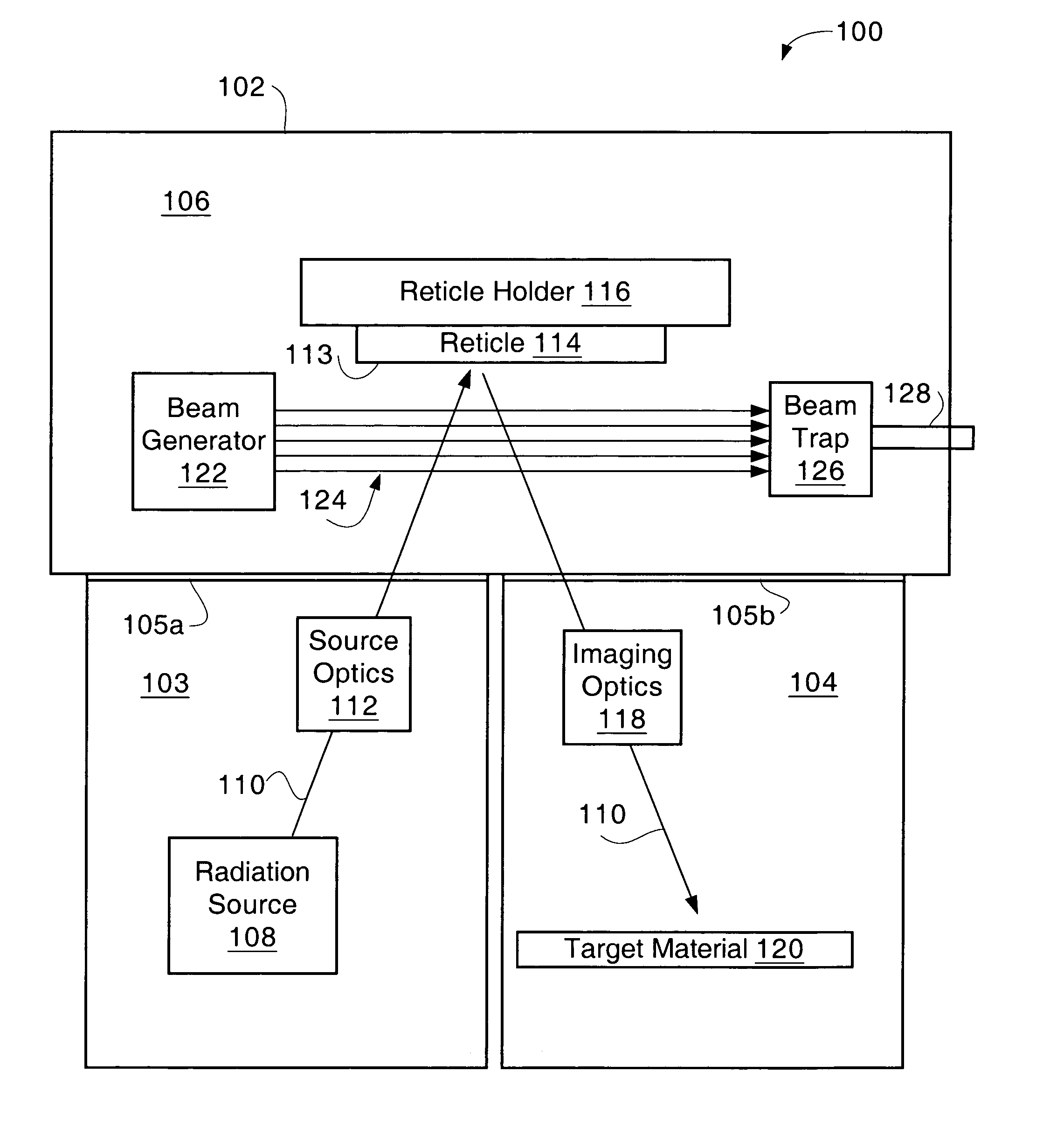
[0007]FIG. 1 is a schematic diagram of a lithography apparatus 100 for patterning a piece of target material 120, such as a silicon substrate, through use of light reflected off a patterned surface of a reticle 114 according to one embodiment of the present invention. The lithography apparatus 100 may include a lithography chamber 102 in which the lithography may take place. In some embodiments, the lithography chamber 102 may be divided into three volumes, a first volume 103, a second volume 104, and a third volume 106.

[0008]The first volume 103 may enclose a radiation source 108 and source optics 112, and thus may be referred to as a “source volume” or “source optics volume.” The radiation source 108 may be capable of producing electromagnetic radiation 110 used with the reticle 114 to pattern the target material 120. In some embodiments, the radiation source 120 may produce extreme ultraviolet light (EUV), such as light with a wavelength less than about 15 nanometers and greater ...


PUM

PropertyMeasurementUnit
energyaaaaaaaaaa
distanceaaaaaaaaaa
pressureaaaaaaaaaa

Abstract

Embodiments of the invention provide a beam generator to produce an atomic beam that travels across a patterned surface of a reticle. The beam may interact with particles to prevent the particles from contaminating the reticle.

Description

BACKGROUNDBackground of the Invention[0001]Lithography is used in the fabrication of semiconductor devices. In lithography, a light sensitive material called a “photoresist” coats a wafer substrate, such as a silicon substrate. The photoresist may be exposed to light reflected from or transmitted through a mask, called a “reticle”, to reproduce a pattern from the reticle on the substrate. If the reticle is contaminated, such as by unwanted particles on the surface of the reticle, the pattern of light reflected from the reticle, and thus the pattern formed on the substrate, may not be the desired pattern. This may lead to failures of microelectronic or other devices formed on the substrate.BRIEF DESCRIPTION OF THE DRAWINGS[0002]FIG. 1 is a cross sectional schematic of a lithography apparatus according to one embodiment of the present invention.[0003]FIG. 2a is a cross sectional schematic of a lithography apparatus that illustrates particles that may contaminate the patterned surface ...

Claims


Application Information

Patent Timeline
Patent Type & Authority Patents(United States)
IPC IPC(8): G03F7/20H05H3/02
CPCG03F7/70866H05H3/02G03F7/70916G03F7/70983
Inventor SILVERMAN, PETER J.
Owner INTEL CORP
Why Eureka
Try Eureka