Heat radiating sheet

a technology of heat radiating sheet and heat radiating material, which is applied in the direction of indirect heat exchangers, laminated elements, light and heating apparatus, etc., can solve the problems that the electrical component that emits heat by itself, like a cpu, may possibly operate improperly, etc., and achieve the effect of reducing the proportion of resin material and increasing thermal conductivity

Active Publication Date: 2019-05-14
TOYOTA JIDOSHA KK
View PDF6 Cites 0 Cited by
  • Summary
  • Abstract
  • Description
  • Claims
  • Application Information

AI Technical Summary

Benefits of technology

[0009]Therefore, in the conventional heat radiating sheet 20 with such a configuration, it is unavoidable that the function of a heat conduction path will differ between the portions of the expanded sheet 10 where the connecting portions 4 are located and where the strand portions 5 are located. Consequently, when the heat radiating sheet 20 is seen as a whole, formation of a heat conduction path by the heat radiating member 10 unavoidably becomes insufficient, and in order to increase thermal conductivity, it would be necessary to increase the proportion of the heat radiating member 10 to the heat radiating sheet 20. This means that the proportion of the resin material should lowered, which can sacrifice the flexibility of the heat radiating sheet 20.

Problems solved by technology

An electronic component that emits heat by itself, like a CPU, may possibly operate improperly when it is overheated.

Method used


Image

  • Heat radiating sheet
  • Heat radiating sheet
  • Heat radiating sheet

Examples


embodiment 1

Another Embodiment 1

[0051]FIG. 9 shows another embodiment of a heat radiating sheet. A heat radiating sheet 200a herein differs from the aforementioned heat radiating sheet 200 in that an insulating layer 101 is provided on each of the front and rear surfaces of the heat radiating sheet 100. The other structures are the same as those of the heat radiating sheet 200. As a material of the insulating layer 101, it is possible to use thermosetting resin such as silicone resin, epoxy resin, or urethane resin; a resin material such as polyamide resin, polyphenylene sulfide resin, or polyimide resin; or ceramic materials such as alumina, silica, or boron nitride. Providing the insulating layer 101 can obtain the heat radiating sheet 200 that ensures both high thermal conductivity and insulating property.

embodiment 2

Another Embodiment 2

[0052]FIG. 10 shows further another embodiment of a heat radiating sheet. In a heat radiating sheet 200b herein, a heat radiating member 100 is formed using as the original sheet 50 a member that has an insulating film 102 formed on each of the front and rear surfaces thereof. As a material of the insulating film 102, it is possible to use thermosetting resin such as silicone resin, epoxy resin, or urethane resin; a resin material such as polyamide resin, polyphenylene sulfide resin, or polyimide resin; or ceramic materials such as alumina, silica, or boron nitride. Such an insulating sheet 200b can also ensure both high thermal conductivity and insulating property since the heat radiating member 100 per se has insulating performance.

examples

[0053]Hereinafter, the advantages of the heat radiating sheet 200 in accordance with the present disclosure will be described with reference to Examples and Comparative Examples.

Products of Examples

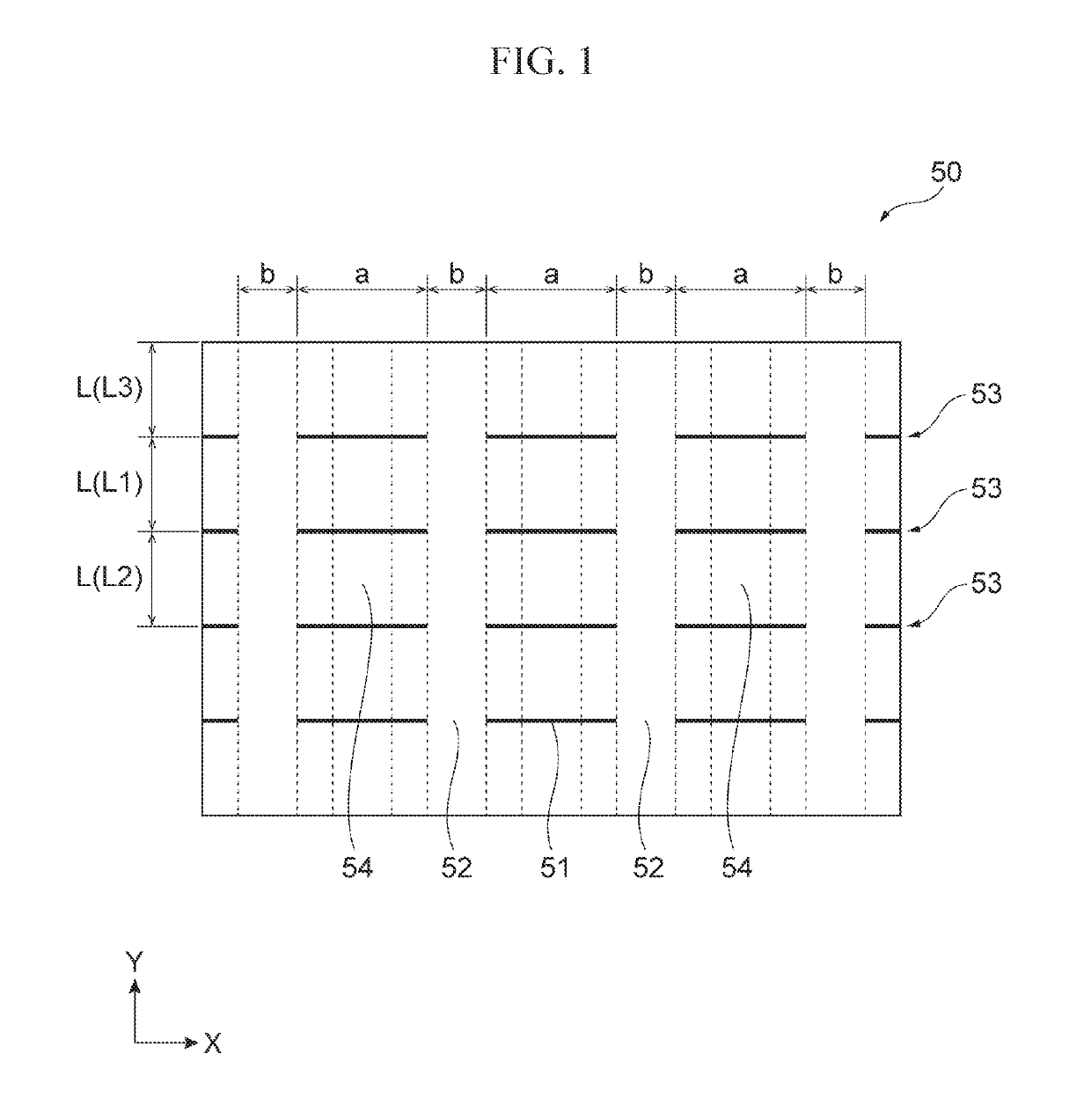
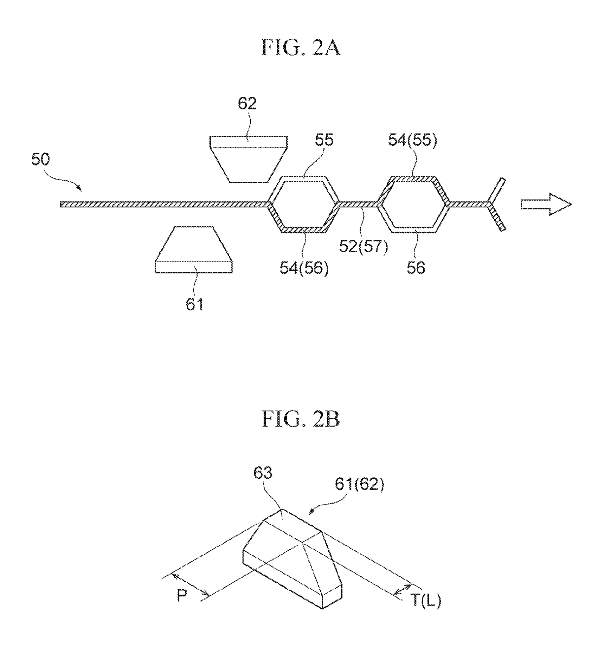
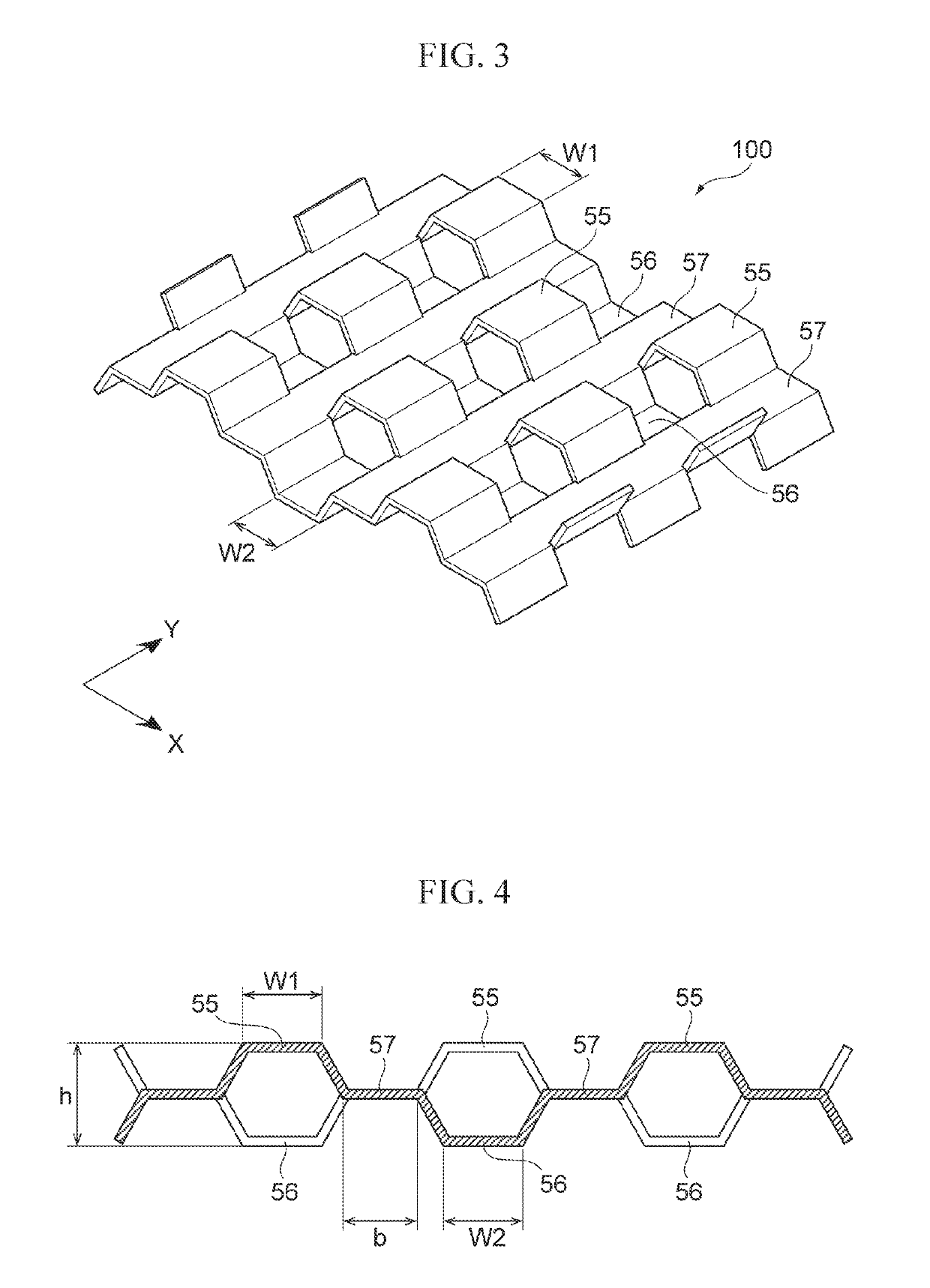
[0054]A slitting process and press work were performed on a pure Cu foil with a thickness of 200 μm that is the original thin sheet 50 so that the heat radiating member 100 with the shape shown in FIG. 3 whose specific dimensions are shown in Examples 1, 2, and 3 of Table 1 was produced. Then, as shown in FIGS. 6 and 7, the heat radiating member 100 produced was buried in liquid silicone resin as the resin material 300, and the resin material 300 was thermally cured in a constant-temperature oven so that the heat radiating sheet 200 was obtained.

[0055]As shown in Table 1, in each of Examples 1, 2, and 3, the dimensions and shape of the heat radiating member 100 were changed so that the volume fraction of the heat radiating member (Cu) relative to the heat radiating sheet 200 was made diff...


PUM

PropertyMeasurementUnit
thermal conductivityaaaaaaaaaa
volume fractionaaaaaaaaaa

Abstract

Provided is a flexible heat radiating sheet with high thermal conductivity. The heat radiating sheet includes a resin material and a heat radiating member that extends in the planar direction and has a required thickness. The heat radiating member is bent such that in portions of a thin plate member between adjacent slit rows, projecting portions and recess portions are alternately repeated in the X-axis direction, and a projecting portion and a recess portion that are adjacent in the Y-axis direction are located facing each other. The heat radiating member is entirely buried in the resin material excluding apexes of the projecting portions and the recess portions.

Description

CROSS REFERENCE TO RELATED APPLICATIONS[0001]The present application claims priority from Japanese patent application JP 2017-010176 A filed on Jan. 24, 2017, the content of which is hereby incorporated by reference into this application.BACKGROUNDTechnical Field[0002]The present disclosure relates to a heat radiating sheet that is suited for radiating heat generated from, for example, a heat-generating electronic component to the outside.Background Art[0003]An electronic component that emits heat by itself, like a CPU, may possibly operate improperly when it is overheated. In order to avoid this, a suitable cooling device is used together with the electronic component. Examples of such a cooling device include a heat radiating sheet disclosed in JP 2001-291810 A and a heat transfer device disclosed in JP 2011-086753 A.[0004]The heat radiating sheet disclosed in JP 2001-291810 A includes a thermally conductive adhesive layer, which contains matrix resin and thermally conductive fill...

Claims


Application Information

Patent Timeline
Patent Type & Authority Patents(United States)
IPC IPC(8): F28F7/00F28F13/18H05K7/20F28F3/02H01L21/48H01L23/367H01L23/373F28D21/00
CPCH05K7/20418F28F3/027F28F13/18H01L21/4878H01L23/3672H01L23/3737F28F2255/146C09J2477/00F28D2021/0029F28F2245/06F28F2255/06F28F2255/12B32B2307/302H01L23/3735H01L23/3736
Inventor YOSHIDA, YUJI
Owner TOYOTA JIDOSHA KK
Why Eureka
Try Eureka