Supercharge Your Innovation With Domain-Expert AI Agents!

Tissue repair system

a tissue repair and tissue technology, applied in the field of tissue repair systems, can solve the problems of reducing the repair efficiency of all-in-one technique, so as to eliminate the need for additional incisions

Active Publication Date: 2019-05-28
YAMADA RONALD
View PDF16 Cites 1 Cited by
  • Summary
  • Abstract
  • Description
  • Claims
  • Application Information

AI Technical Summary

Benefits of technology

The present invention is a delivery apparatus for repairing meniscal tear in knees. It includes a straight or angulated delivery cannula with a fixture for connection to a line. The delivery cannula has a compartment for holding the implant and can be pulled or kedged to deliver the implant across the tear. The apparatus ensures accurate alignment and depth of the implant relative to the tear. The technical effects of the invention are improved repairing of meniscal tear with improved alignment and accuracy of depth of the implant.

Problems solved by technology

Both techniques requiring outside incisions increase the risk of injury to vulnerable tissues.
However, instruments of the prior art limit a successful all-inside technique repair to a narrow range of tears.
Pushing an instrument obliquely to the optimal perpendicular angle of insertion generates a deforming lateral shear force at the tear site and produces a buckled, deformed, and weak repair.
Moreover, prior art instruments can be utilized in only a limited area (posterior) of a meniscus because anatomic constraints prevent optimal alignment of instrument with a tear.
However, when such handle is ‘pushed’ to advance instrument at a tear site, the distal tip advances along the axis of instrument handle and not along the axis of the angulated distal tip.
Since the axis of the handle diverges from correct direction of insertion, a lateral shear force is generated at the tear as the implant is ‘pushed’ across tear, again creating a deformed and weak repair.
In addition, a practitioner pushing an instrument of the prior art can misperceive resistance during insertion of the instrument tip.
As a result, an implant may be inserted at an improper depth.
Over penetration of an implant risks damage to adjacent structures, while under penetration risks poor fixation and weakened repair.

Method used


Image

  • Tissue repair system
  • Tissue repair system
  • Tissue repair system

Examples


Embodiment Construction

[0052]Various aspects of the present application will evolve from the following detailed description of the preferred embodiments thereof.

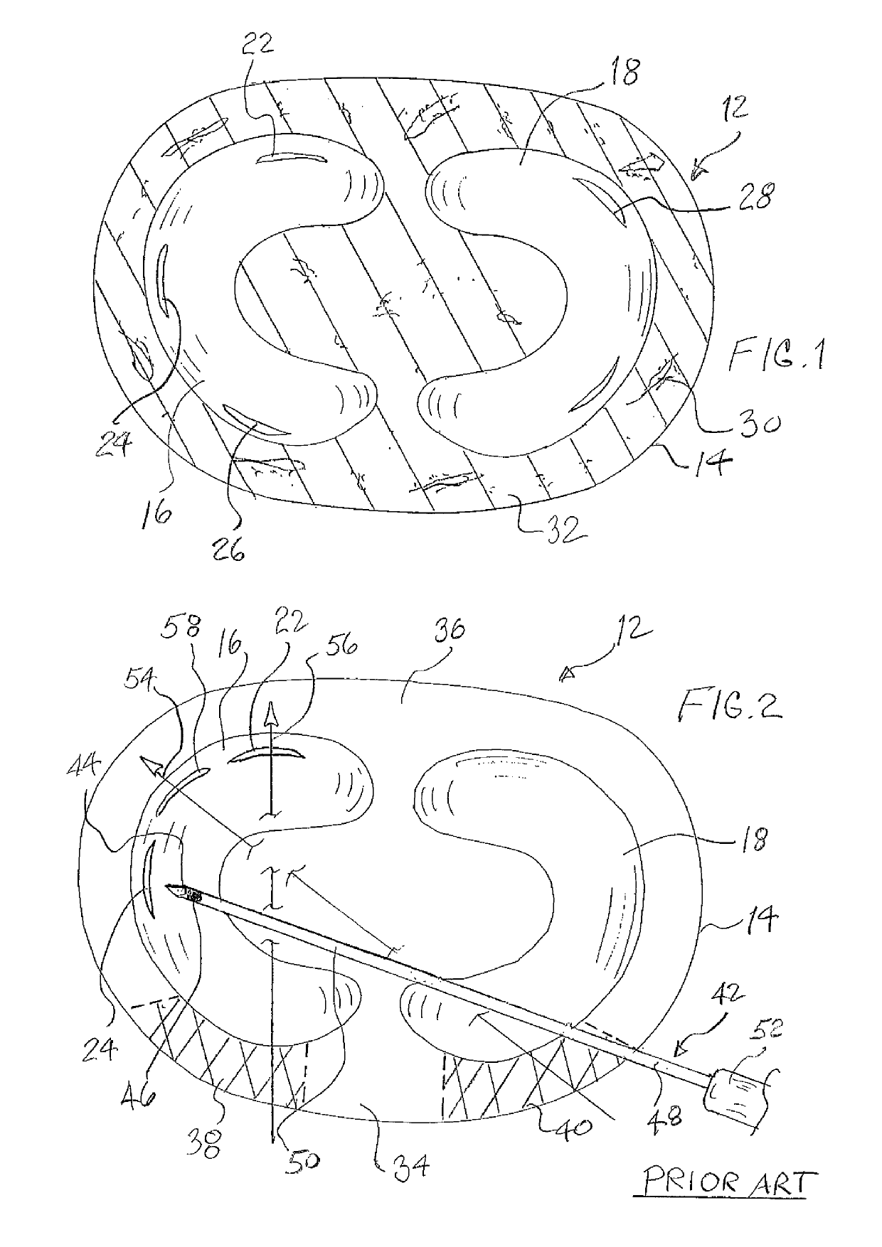
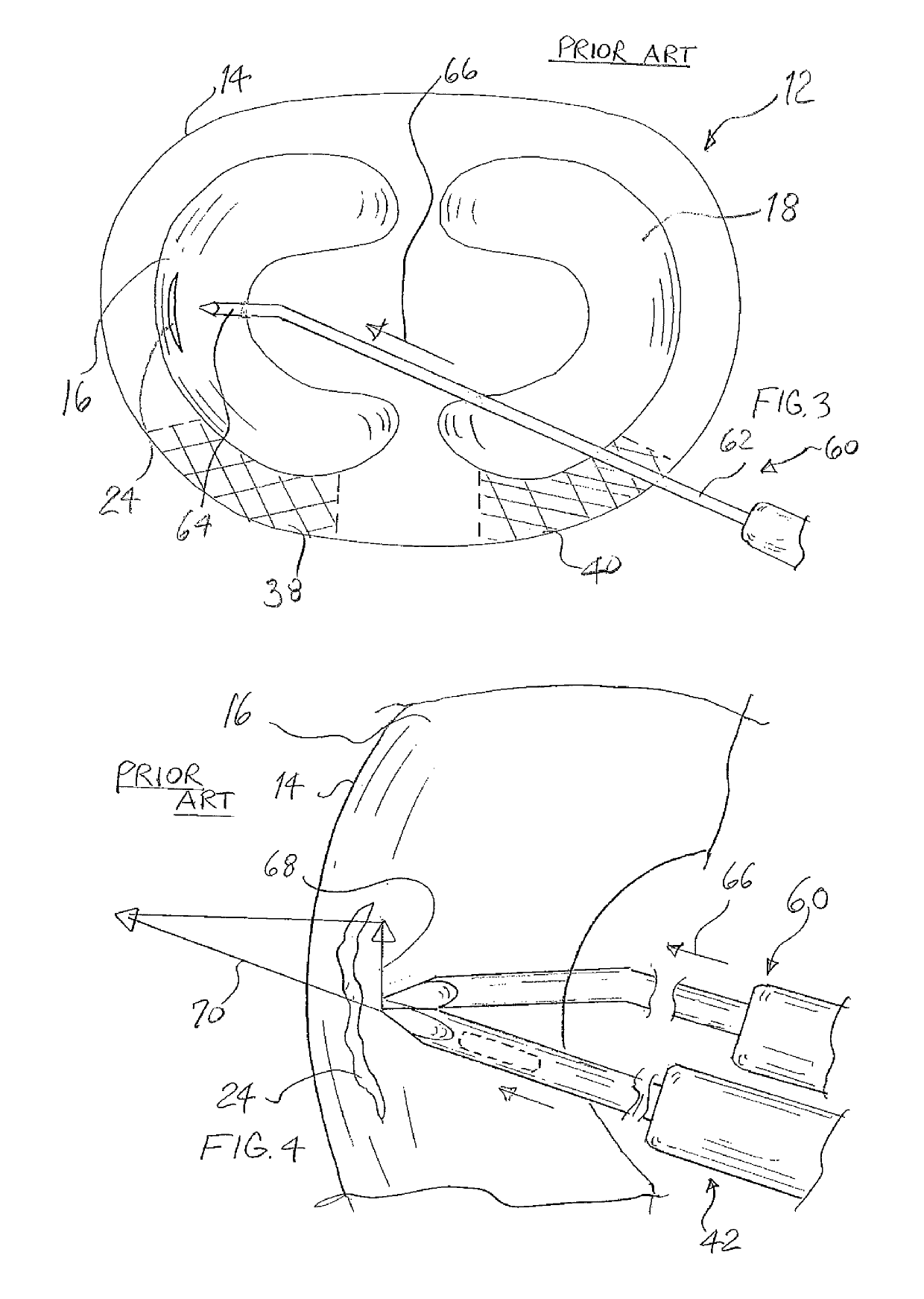
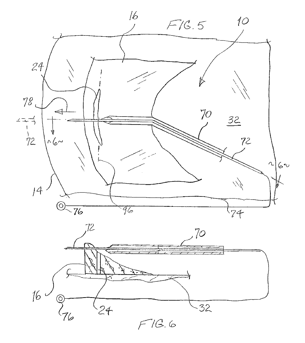
[0053]With respect to FIG. 1, it may be observed that a schematic view of a section of a human knee 12 is shown. Knee 12 includes a skin layer 14 and a pair of menisci 16 and 18. A plurality of representative meniscal tears 20 are also illustrated and are generally located in the peripheral third of each meniscus 16, 18. For example, meniscus 16 includes a posterior horn tear 22, a mid-body tear 24, and an anterior horn tear 26. Likewise, meniscus 18 exhibits a mid-body posterior tear 28 and an anterior mid-body tear 30. Again, the plurality of tears 20 exhibited in FIG. 1 are simply being employed as models for the following discussion of the novel apparatus of the present application. Portion 32 of knee 12 represents other anatomical structures within the knee such as bones, blood vessels, ligaments, and the like. Needless to say, knee 12 is rep...


PUM


Abstract

An apparatus for repairing an anatomical tear, such as a tear in the meniscus of a human knee. The apparatus includes a guide cannula directing a penetrating shaft through the meniscal tear and through the outer skin layer of the knee. The penetrating shaft pulls a line to the outside of the skin layer of the knee where it is used to pull or kedge a repair implant into position across the meniscal tear.

Description

BACKGROUND OF THE INVENTION[0001]The present invention relates to a novel and useful apparatus or system for repairing a tear in an anatomical structure such as soft and connective tissue. For example, a meniscus tear may be the subject of use of the apparatus of the present application in the human knee.[0002]A meniscus tear is a common injury caused by forceful twisting of the knee, usually during participation in vigorous or sports activities. Each knee of a human anatomy includes a pair of menisci. Each meniscus is a rubbery C-shaped disc that cushions the knee and provides steadiness during ambulatory motion.[0003]Surgery is often performed to repair tears in a meniscus by the use of implants such as darts, anchors, sutures and other devices. Such surgery is desirable to maintain meniscal cushioning and stability of the knee joint and prevent premature arthritis.[0004]Repair of a tear in a meniscus can be performed sing various techniques, such as open, arthroscopic with extern...

Claims


Application Information

Patent Timeline
Patent Type & Authority Patents(United States)
IPC IPC(8): A61B17/04A61B17/068A61B17/34A61B17/12A61B17/22A61B17/064A61B17/06
CPCA61B17/3468A61B17/0482A61B17/068A61B17/12A61B17/3403A61B2017/3409A61B2017/0646A61B2017/0647A61B2017/06095A61B2017/22044A61B2017/061
Inventor YAMADA, RONALD
Owner YAMADA RONALD
Features
  • R&D
  • Intellectual Property
  • Life Sciences
  • Materials
  • Tech Scout
  • Unparalleled Data Quality
  • Higher Quality Content
  • 60% Fewer Hallucinations
Learn More