System and method for implant delivery

a technology of implanting device and system, which is applied in the field of system and method of implanting device, can solve the problems of inability to position the implant in relation to the heart by rotating the proximal end of the catheter, and achieve the effect of reducing the number of joints and high degree of torsional rigidity

Active Publication Date: 2019-05-28
ABBOTT CARDIOVASCULAR
View PDF8 Cites 96 Cited by
  • Summary
  • Abstract
  • Description
  • Claims
  • Application Information

AI Technical Summary

Benefits of technology

[0005]In one embodiment, the invention is a method of delivering an implant into a heart of a patient, the heart having a left atrium and a right atrium. The method comprises creating an entryway into the anatomy of a patient via a femoral artery. Then a trans-septal puncture is performed between the right atrium and the left atrium. A catheter is inserted into the patient via the femoral artery. The catheter has a proximal end communicating via a bore to a distal end. The catheter has a first joint, and a second joint that is located distal of the first joint, wherein, the first joint and the second joint are separated by a first digit that is rotationally rigid at all points between the first joint and the second joint, and further wherein the second joint and the distal end are separated by a second digit that is rotationally rigid at all points between the second joint and the distal end. The catheter is advanced into the patient until the first joint and the distal end are located in the right atrium and an implant is located, within the bore, distal of the first joint. The first joint is bent. The distal end is passed via the trans-septal puncture into the left atrium until the second joint is located in the left atrium. The implant is moved within the catheter until the implant is located distal of the second joint. One of ordinary skill will appreciate that securing an implant at a location adjacent the distal end of a delivery catheter, inside the left atrium, without having been obliged to push the implant around a number of tortuous bends inside a catheter, is a highly advantageous outcome.
[0009]In further embodiments, the second digit includes a conical portion that is flexible in a radial direction. This aspect permits an implant to be forced distally into and through the conical portion, while the conical portion can expand radially to permit passage of the implant. In yet further embodiments, the first joint is an articulating joint, and the articulating joint may include a pin. In further embodiments, the first joint and the second joint are the only joints in the shaft between the proximal end and the distal end. One of ordinary skill will appreciate that by reducing the number of joints, a catheter is formed that has a high degree of torsional rigidity, and permits an operator to rely on that rigidity to position an implant at the distal end, while manipulating the catheter from the proximal end which extends outside the patient.

Problems solved by technology

One of ordinary skill will appreciate that the ability to position the implant in relation to the heart by rotating the proximal end of the catheter is not feasible in current catheters because the current catheters are not tortionally rigid enough between distal end and proximal end to permit such control from the proximal end.

Method used


Image

  • System and method for implant delivery
  • System and method for implant delivery
  • System and method for implant delivery

Examples


Embodiment Construction

[0025]As may be understood from this detailed description, as read in conjunction with the figures, a catheter having features of the invention is described. The context of the invention is explained with initial reference to FIGS. 1-5.

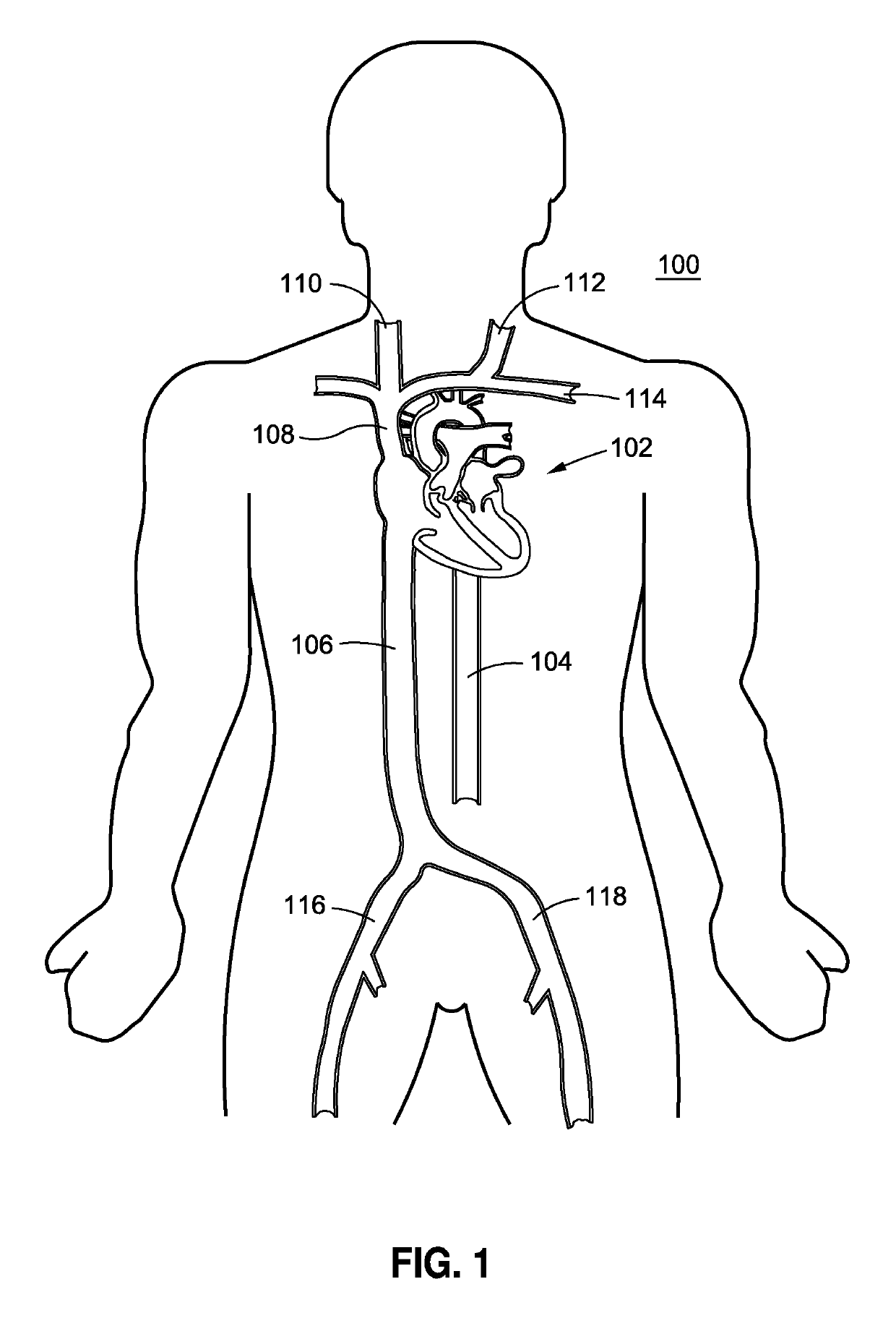
[0026]Referring to FIG. 1, there is shown a schematic frontal illustration, looking posteriorly from the anterior side of the patient 100. The heart 102 is a pump, the outlet of which is the aorta, including the descending aorta 104, which is a primary artery in the systemic circulation. The circulatory system, which is connected to the heart 102 further comprises the return, or venous, circulation. The venous circulation comprises the superior vena cava 108 and the inferior vena cava 106. The right and left jugular veins, 110 and 112, respectively, and the subclavian vein 114 are smaller venous vessels with venous blood returning to the superior vena cava 108. The right and left femoral veins, 116 and 118 respectively, return blood from the legs to t...


PUM


Abstract

A method for delivering an implant including, a catheter having a shaft defined by a proximal end and a distal end and a bore extending therethrough; a first joint in the shaft, and a second joint in the shaft located distal of the first joint. The first joint and the second joint are separated by a first digit sized to receive the implant and located between the first joint and the second joint. The second joint and the distal end are separated by a second digit being sized to receive the implant. The implant is advanced through the first digit and into the second digit without bending the implant or the first and second digits by rotating the digits at the first joint and the second joint.

Description

BACKGROUND[0001]This application relates to systems and methods for implanting devices such as replacement heart valves, clips, stents, and similar repair devices within the anatomy of a patient.[0002]It is well known in the art to implant devices such as replacement heart valves, clips, stents, and reinforcement rings, and the like into the human heart to repair the function of the human heart. Similar devices are also introduced into other parts of the human anatomy where mechanical repair is needed. Many such repair operations are carried out by first inserting a delivery catheter by minimally invasive means into a desired organ of the human anatomy. Thereafter, a repair device is passed through an internal lumen along the entire length of the delivery catheter until the repair device reaches the target organ, and the device is pushed out of the distal end of the catheter for implantation. Such devices may expand to assume a new shape once they are pushed out of the delivery cath...

Claims


Application Information

Patent Timeline
Patent Type & Authority Patents(United States)
IPC IPC(8): A61F2/24
CPCA61F2/2427A61F2210/0057A61F2/2436A61F2/2466A61F2/95
Inventor KIZUKA, KOJI J.
Owner ABBOTT CARDIOVASCULAR
Why Eureka
Try Eureka