
Cardiac tissue penetrating devices, methods, and systems for treatment of congestive heart failure and other conditions

a technology of cardiac tissue and penetrating device, which is applied in the field of cardiac tissue penetrating device, methods and systems for treating congestive heart failure and other conditions, can solve the problems of affecting the normal functioning of the heart muscle, so as to achieve the effect of progressively replacing more and more contractile heart tissu

Active Publication Date: 2019-06-11
BIOVENTRIX A CHF TECH
View PDF209 Cites 4 Cited by
  • Summary
  • Abstract
  • Description
  • Claims
  • Application Information

AI Technical Summary

Benefits of technology

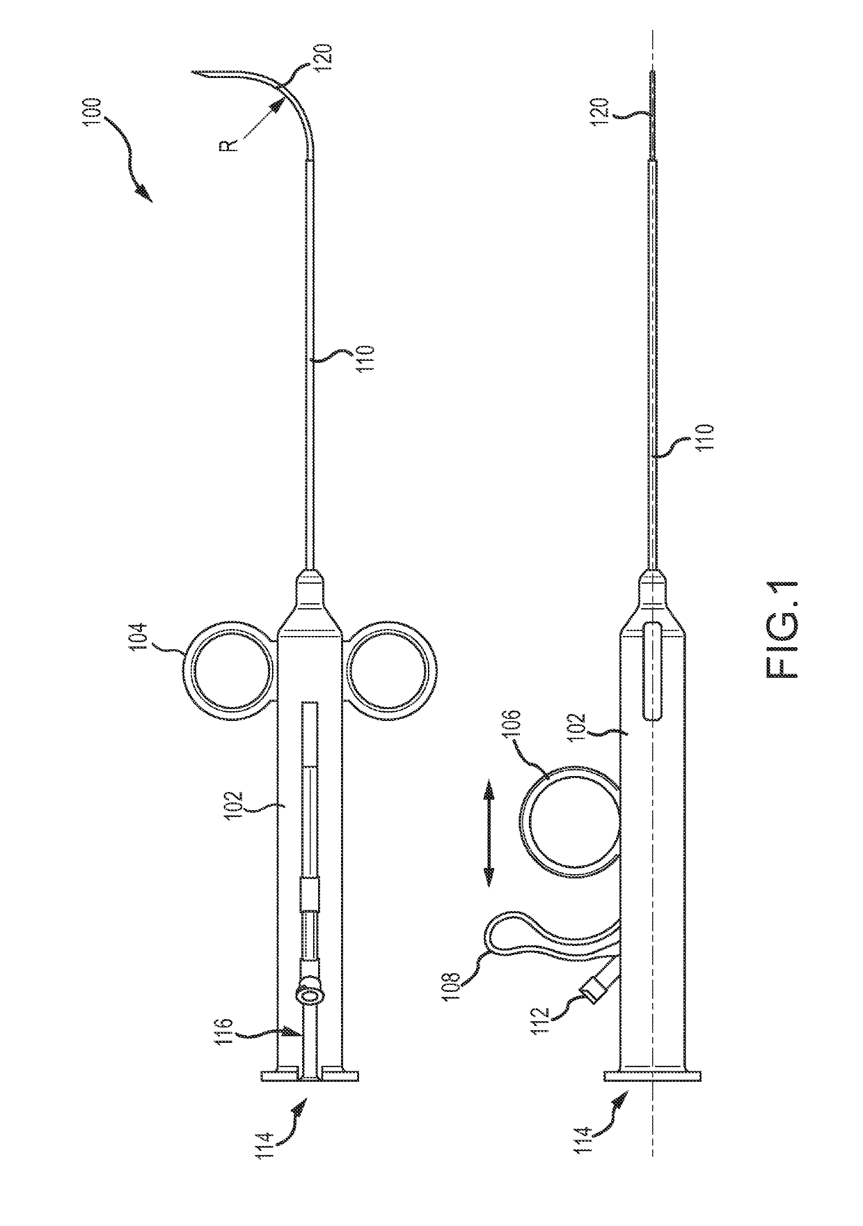
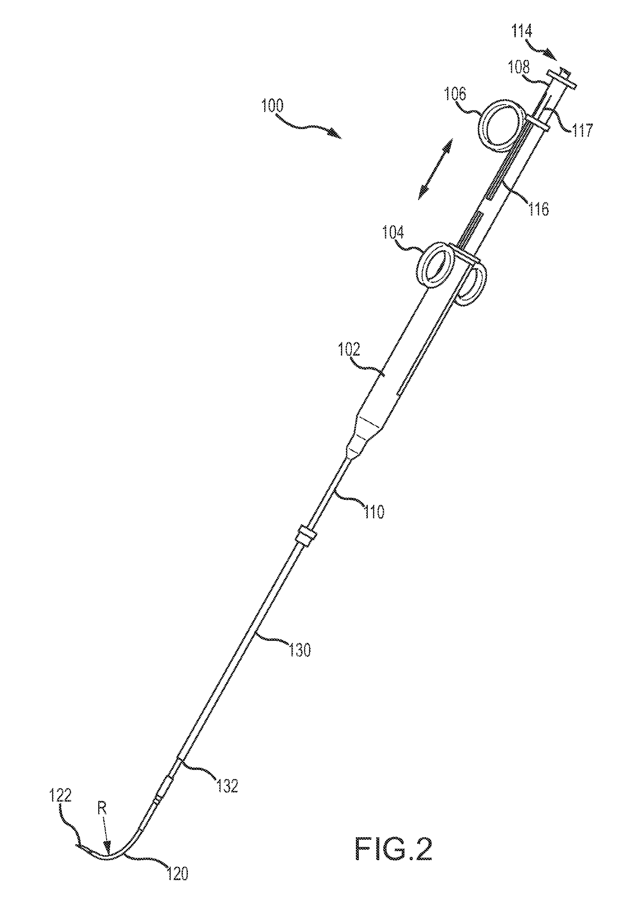
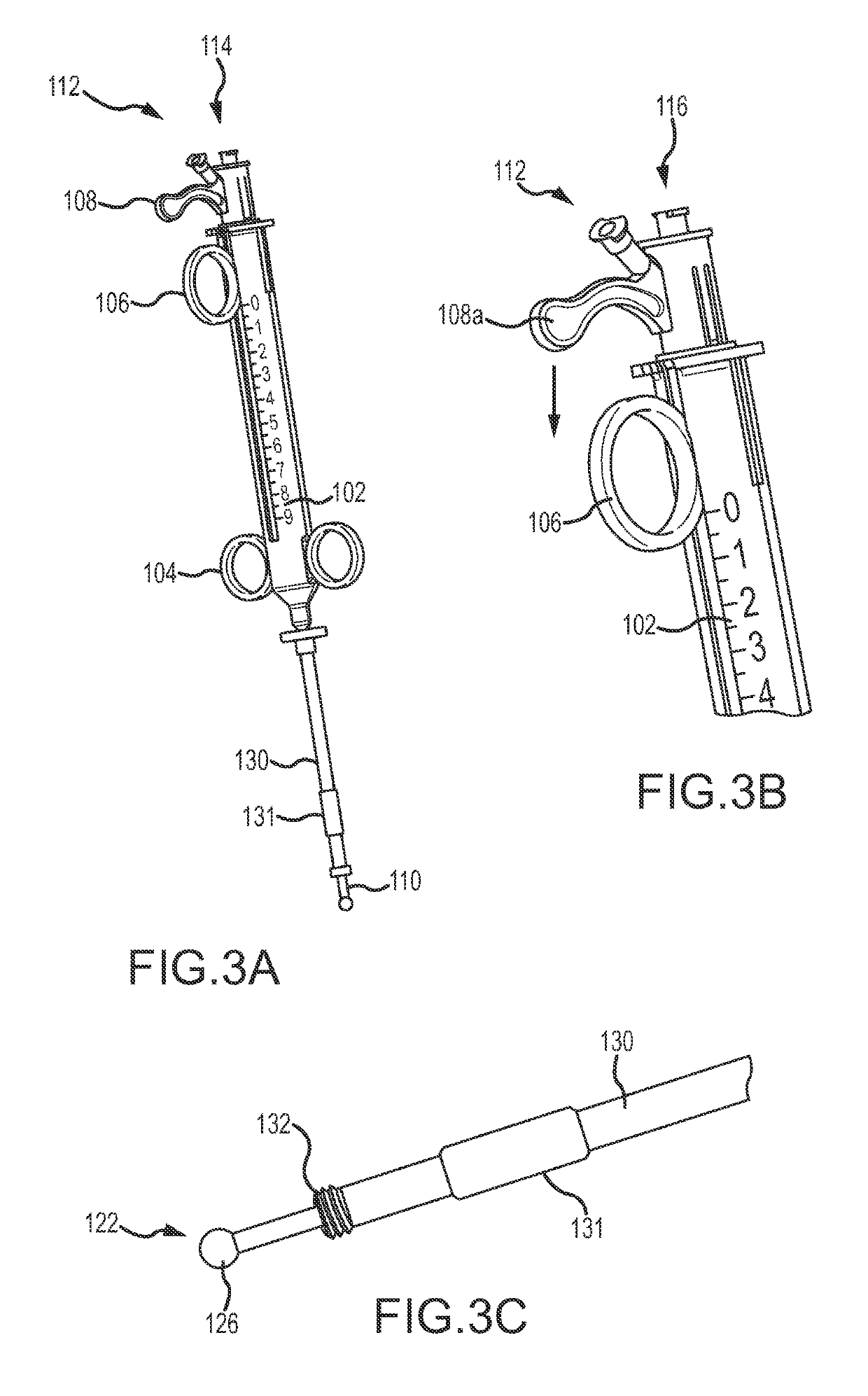
[0011]In some embodiments, the tool body may include a spring trigger mechanism that causes the first needle and / or the second needle to rapidly deploy distally upon actuation of the spring trigger mechanism. In some embodiments, the distal end of the elongate shaft may include a locking mechanism that is couplable with an attachment or tissue anchoring device that may be removably attached to the patient's tissue or organ (e.g., the heart). In some embodiments, when in the second configuration, the first needle may bend or curve away from the axis of the elongate shaft's lumen by between about 45 and 210°. In other embodiments, the first needle may bend or curve away from the axis of the elongate shaft's lumen by between about 80 and 90°. In some embodiments, the distal end of the first needle and / or second needle may include a fluid pathway that allows the user to monitor or measure pressure within the patient's body, such as within a chamber of the heart. Monitoring or measuring pressure may allow the location of the tip of the needle to be determined. For example, left ventricle heart pressure may be monitored or measured, right ventricle heart pressure may be monitored or measured, and / or a damped pressure may be monitored or measured when the needle is imbedded within the wall of the heart (e.g., septum wall). This may allow a physician to determine that the needle tip is near or within the corresponding heart chamber or within heart tissue. In some embodiments, the distal end of the first needle and / or second needle may include a pressure transducer that may be used to sense pressure in or around the patient's tissue or organ, such as in or around the heart as described above.

Problems solved by technology

However, in many cases congestive heart failure may be triggered by a heart attack or myocardial infarction.
Heart attacks can cause scar tissue that interferes with the heart muscle's healthy function, and that scar tissue can progressively replace more and more of the contractile heart tissue.
More specifically, the presence of the scar may lead to a compensatory neuro-hormonal response by the remaining, non-infarcted myocardium leading to progressive dysfunction and worsening failure.
People with heart failure may have difficulty exerting themselves, often becoming short of breath, tired, and the like.
The increased overall volume and higher intracardiac pressures result in congestion in the tissues.
Fluid may also collect in the lungs, interfering with breathing (especially when lying down).
Congestive heart failure may also be associated with a decrease in the ability of the kidneys to remove sodium and water, and the fluid buildup may be sufficient to cause substantial weight gain.
With progression of the disease, this destructive sequence of events can cause the progressive deterioration and eventual failure of the remaining functional heart muscle.
If the heart becomes sufficiently damaged, even more drastic surgery may be considered.
These surgical therapies can be at least partially effective, but typically involve substantial patient risk.
With congestive heart failure, the left ventricle often dilates or increases in size.
This can result in a significant increase in wall tension and stress.

Method used


Image

  • Cardiac tissue penetrating devices, methods, and systems for treatment of congestive heart failure and other conditions
  • Cardiac tissue penetrating devices, methods, and systems for treatment of congestive heart failure and other conditions
  • Cardiac tissue penetrating devices, methods, and systems for treatment of congestive heart failure and other conditions

Examples


Embodiment Construction

[0041]The present invention generally provides improved medical devices, systems, and methods. Exemplary embodiments of the devices are described for use in reducing the distance between a region along the septum and a region of an external wall of the left ventricle of a heart in a less or minimally invasive manner. Hence, embodiments of the tools and methods described herein may find specific use in the treatment of congestive heart failure and other progressive heart diseases by reconfiguring abnormal heart geometry that may be contributing to heart dysfunction. For congestive heart failure therapies, perforating both the exterior wall and the septum from an epicardial approach can provide significant benefits in control over the locations of implant deployments, thereby effectively enhancing the resulting reshaping of the ventricular chamber. Despite this largely epicardial approach, there are surprising benefits to guiding deployment of the implant from along both the epicardia...


PUM


Abstract

According to one embodiment, a tissue penetrating device includes an elongate shaft having a proximal end, a distal end, and a lumen extending there between. A first needle is disposed within the lumen of the elongate shaft and is extendable therefrom between a first configuration and a second configuration. In the first configuration, the first needle is disposed within the elongate shaft's lumen and is substantially aligned with an axis of the lumen. In the second configuration, the first needle extends distally of the elongate shaft's distal end and bends away from the lumen's axis. A second needle is disposed within a lumen of the first needle and is extendable therefrom when the first needle is positioned in the first configuration and when the first needle is positioned in the second configuration. The second needle may be extended from the first needle to penetrate tissue of a patient.

Description

BACKGROUND OF THE INVENTION[0001]The present invention is related to improved medical devices, systems, and methods, with many embodiments being particularly useful for reducing the distance between two points in tissue in a minimally or less invasive manner. Specific reference is made to the treatment of a failing heart, particularly the alleviation of congestive heart failure and other progressive heart diseases. The provided devices, systems, and methods will often be used to resize or alter the geometry of a ventricle in a failing heart, such as by reducing its radius of curvature through the process of excluding a portion of the circumference from contact with blood, and thereby reduce wall stress on the heart and improve the heart's pumping performance. Although specific reference is made to the treatment of congestive heart failure, embodiments of the present invention can also be used in other applications in which tissue geometry is altered.[0002]Exemplary embodiments descr...

Claims


Application Information

Patent Timeline
Patent Type & Authority Patents(United States)
IPC IPC(8): A61F2/24A61B1/005A61B5/06A61B5/0215A61B17/00A61B17/06A61B17/04
CPCA61B5/0215A61B1/0058A61B5/065A61F2/2487A61B17/0487A61F2002/249A61B2017/00247A61B2017/0409A61B2017/0417A61B2017/06052A61B2017/00243
Inventor VAN BLADEL, KEVINMOSHE, MEIRANNEST, LON
Owner BIOVENTRIX A CHF TECH
Learn More