
Method and magnetic resonance apparatus for determining a minimized echo time

a magnetic resonance apparatus and echo time technology, applied in the direction of magnetic measurement, instruments, measurements using nmr, etc., can solve the problem of poor signal-to-noise ratio for substances with an extremely short t2 relaxation time, decayed magnetic resonance signal of these materials/substances, image artifacts, etc., to achieve the effect of shortening the possible echo tim

Active Publication Date: 2019-06-11
SIEMENS HEALTHCARE GMBH
View PDF3 Cites 0 Cited by
  • Summary
  • Abstract
  • Description
  • Claims
  • Application Information

AI Technical Summary

Benefits of technology

The invention allows for faster echo times in magnetic resonance sequences with ultrashort echo times. This is particularly useful in the PETRA magnetic resonance sequence where the center of k-space is scanned in Cartesian form and the external portions of k-space are scanned radially. By dynamically setting the magnetic resonance protocol based on the minimum possible echo time determined from the individual measurement of the center of k-space, the extent of the portion to be measured in Cartesian form can be determined and the magnetic resonance sequence can be dynamically set to the new information. This ensures a minimum measurement time and an optimized magnetic resonance sequence.

Problems solved by technology

These cannot be captured with conventional magnetic resonance sequences that usually make use of an echo time of significantly more than one millisecond, so that the magnetic resonance signal of these materials / substances has already decayed at this point in time.
However, if the user chooses an echo time that is too short, the first points of the readout operation are not measured correctly, resulting in image artifacts.
However, this means that in most cases the actual possible minimum echo time cannot be set, resulting in a poorer signal-to-noise ratio for substances with an extremely short T2 relaxation time, as well as a longer measurement time for example in the PETRA sequence, since in that case a larger central portion of k-space has to be captured in Cartesian form.
By providing minimum possible echo times that should work with a sufficient buffer for all radio-frequency coils, it may nevertheless occur that when using older radio-frequency coils the minimum possible echo time is not long enough to prevent image artifacts.

Method used


Image

  • Method and magnetic resonance apparatus for determining a minimized echo time

Examples


Embodiment Construction

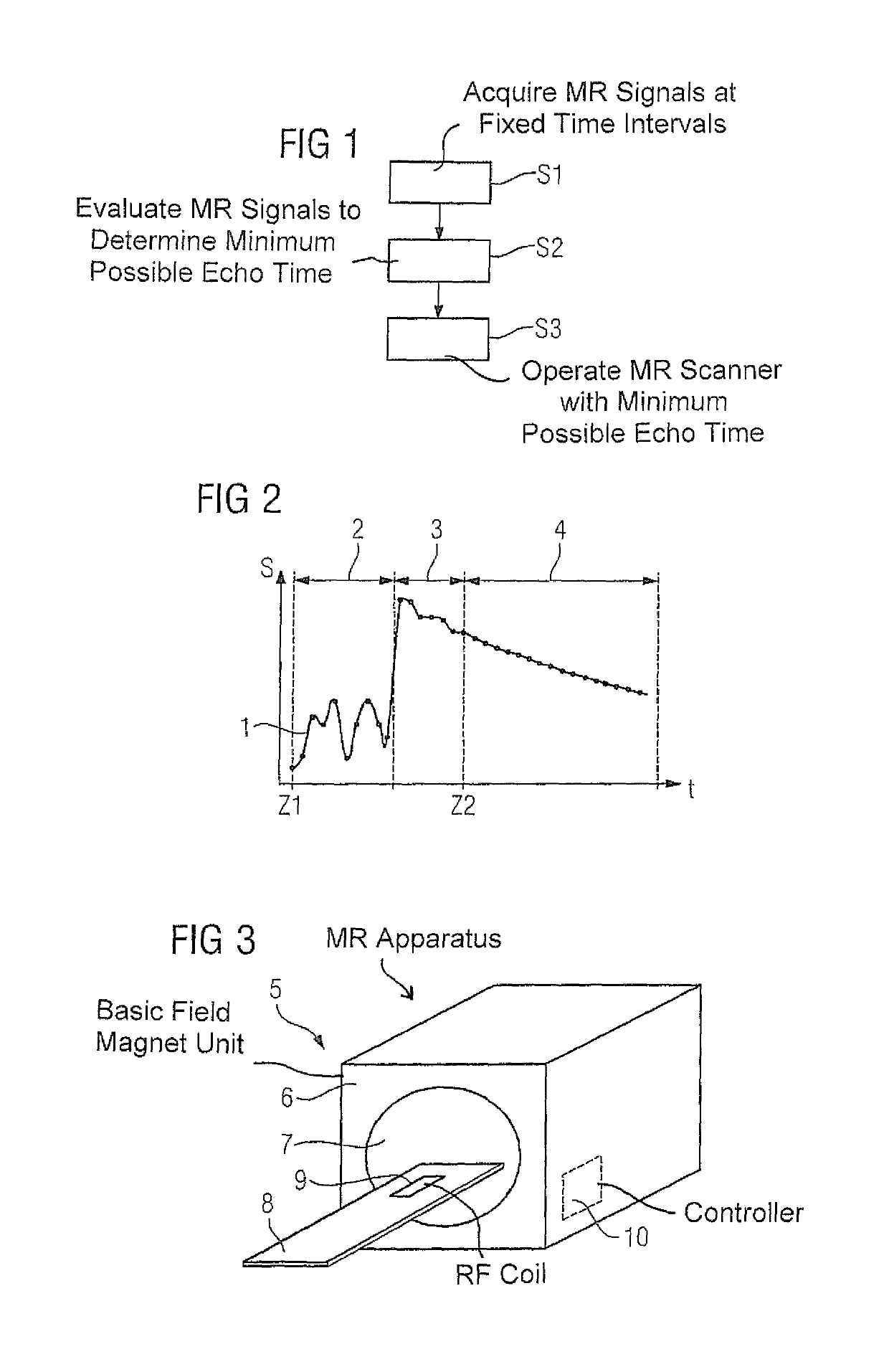
[0025]FIG. 1 shows a basic flowchart of exemplary embodiments of the inventive method. In a step 1 a magnetic resonance measurement is performed, a free induction decay being recorded in a single repetition with a radio-frequency coil, by measuring magnetic resonance signals at fixed time intervals, in this case of 2 μs. In this exemplary embodiment the magnetic resonance measurement starts immediately after the termination of the excitation pulse which precedes it.

[0026]In step S2 the time series of magnetic resonance signals is evaluated, in order to determine a minimum possible echo time in the combination of magnetic resonance device used and radio-frequency coil for the data recording to be performed. To this end the measurement instant (point in time) should be determined, from which an exponential signal decay was measured.

[0027]One possible profile 1 of the measured magnetic resonance signal S of a free induction decay with respect to time t is shown in FIG. 2. The points al...


PUM


Abstract

In a method for determining a minimum possible echo time for a radio-frequency coil used in a magnetic resonance scanner, magnetic resonance signals are acquired with the radio-frequency coil in a magnetic resonance measurement of a free induction decay at fixed time intervals, the minimum possible echo time being determined by evaluating the time series of magnetic resonance signals as the instant from which an exponential signal decay was measured.

Description

BACKGROUND OF THE INVENTION[0001]Field of the Invention[0002]The invention concerns a method for determining an echo time that is as minimum as possible for a radio-frequency coil used in a scanner of a magnetic resonance apparatus, and a magnetic resonance apparatus for implementing such a method.[0003]Description of the Prior Art[0004]The advantages of magnetic resonance sequences with “ultrashort” echo times (TE) are widely discussed. Ultrashort echo times are understood in the art as meaning echo times that are shorter than 500 μs. Magnetic resonance sequences with ultrashort echo times open new potential applications for magnetic resonance imaging, since they also enable magnetic resonance signals of substances that have very short T2 or T2* relaxation times to be measured and displayed. For example, bones, tendons, ligaments, teeth, lung tissue, etc., can be visualized. These cannot be captured with conventional magnetic resonance sequences that usually make use of an echo tim...

Claims


Application Information

Patent Timeline
Patent Type & Authority Patents(United States)
IPC IPC(8): G01R33/48G01R33/54
CPCG01R33/4816G01R33/543G01R33/482
Inventor GRODZKI, DAVID
Owner SIEMENS HEALTHCARE GMBH
Learn More