Method for manufacturing a refractory part made of composite material

a composite material and refractory part technology, applied in the direction of blade accessories, engine components, machines/engines, etc., can solve the problems of poor delamination performance, poor mechanical properties of composite materials of those types, and inability to withstand shear forces well, so as to achieve the effect of improving mechanical properties and high volume fraction of the matrix

Active Publication Date: 2019-06-25
SAFRAN
View PDF11 Cites 2 Cited by
  • Summary
  • Abstract
  • Description
  • Claims
  • Application Information

AI Technical Summary

Benefits of technology

[0011]An object of the present invention is to remedy the above-mentioned drawbacks and to propose a solution that makes it possible to make parts out of composite material, in particular of oxide / oxide type or of CMC type, from a fiber texture that is thick and / or of complex shape, and to do in a manner that is fast and reliable, while giving good control over the deposition and the distribution of solid particles within the fiber texture in order to obtain a material with a very small content of macropores.
[0021]By using a part made of porous material suitable for draining the liquid of the slip, the method of the invention makes it possible to eliminate the liquid phase from the slip that is introduced into the fiber texture without eliminating the refractory solid particles that are also present in the texture. Eliminating the solid phase of the slip by draining also makes it possible to avoid disturbing the distribution of refractory particles within the fiber texture, and consequently to obtain a composite material part with a high volume fraction for the matrix. Consequently, the part made of thermostructural composite material presents improved mechanical properties.

Problems solved by technology

Nevertheless, that type of preparation method is suitable only for making CMC or oxide / oxide composite material parts that are of small thickness and that have two-dimensional (2D) fiber reinforcement.
The mechanical characteristics of composite materials of those types remain limited in certain directions.
In particular, those materials present poor delamination performance and they do not withstand shear forces well.
Nevertheless, in the context of making a part out of CMC or oxide / oxide material, those methods present certain drawbacks.
Specifically, impregnating a fiber texture of complex shape and great thickness cannot be performed using an infusion type method, since it does not enable a pressure gradient to be reached that is sufficient for obtaining good impregnation throughout the texture.
The APS type method does not provide fine control over the quantity of matrix that is introduced into the preform.
Furthermore, evaporating the solvent is difficult, since the solvent needs to be removed from the preform without disturbing the distribution of solid particles (refractory oxide, carbide, boride, nitride, etc.) that have been deposited by the slip.
Specifically, while drying the impregnated preform, evaporating and discharging the solvent can lead to particles being entrained with the solvent and / or can modify the distribution of the particles in the preform and can lead to large pores appearing in the final material because of the lack of matrix at certain locations.

Method used


Image

  • Method for manufacturing a refractory part made of composite material
  • Method for manufacturing a refractory part made of composite material

Examples


Embodiment Construction

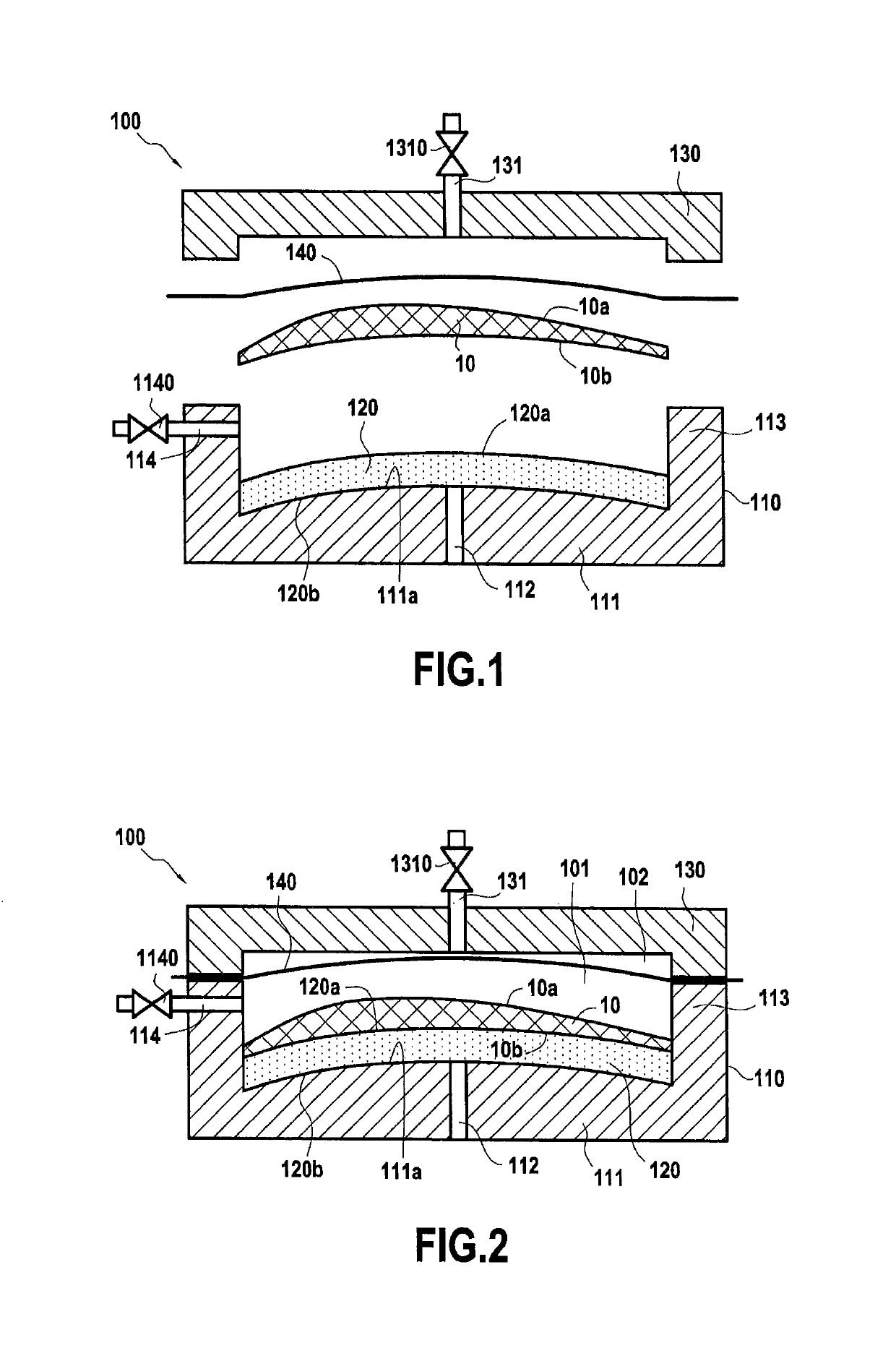
[0033]The method of the present invention for fabricating a part out of composite material, and in particular out of oxide / oxide type or CMC type composite material, begins by making a fiber texture that is to form the reinforcement of the part.

[0034]The fiber structure is made in known manner by using a Jacquard type loom to weave a bundle of warp yarns or strands occupying a plurality of layers, with the warp yarns being interlinked by weft yarns, or vice versa. The fiber texture may be made by stacking plies obtained by two-dimensional (2D) weaving. The fiber texture may also be made directly as a single part by three-dimensional (3D) weaving. The term “two-dimensional weaving” is used herein to mean a conventional method of weaving in which each weft yarn passes from one side to the other of yarns in a single layer of warp yarns, or vice versa. The method of the invention is particularly suited to enabling a filled slip to be introduced into 2D fiber textures, textures obtained ...


PUM

PropertyMeasurementUnit
thicknessaaaaaaaaaa
thicknessaaaaaaaaaa
thicknessaaaaaaaaaa

Abstract

A method of fabricating a part out of composite material, includes forming a fiber texture from refractory fibers; placing the texture in a mold having an impregnation chamber including in its bottom portion a part made of porous material, the impregnation chamber being closed in its top portion by a deformable impermeable diaphragm separating the impregnation chamber from a compacting chamber; injecting a slip containing a powder of refractory particles into the impregnation chamber; injecting a compression fluid into the compacting chamber, to force the slip to pass through the texture; draining the liquid of the slip via the porous material part, while retaining the powder of refractory particles inside the texture so as to obtain a fiber preform filled with refractory particles; drying the fiber preform; unmolding the preform; and sintering the refractory particles present in the preform in order to form a refractory matrix in the preform.

Description

CROSS REFERENCE TO RELATED APPLICATIONS[0001]This application is the U.S. National Stage of PCT / FR2015 / 053618 filed Dec. 18, 2015, which in turn claims priority to French Application No. 1463281, filed Dec. 23, 2014. The contents of both applications are incorporated herein by reference in their entirety.BACKGROUND OF THE INVENTION[0002]The present invention relates to a method of fabricating a part out of thermostructural composite material, in particular of the oxide / oxide type or of the ceramic matrix composite (CMC) type, i.e. comprising fiber reinforcement made of fibers of refractory material and densified with a matrix that is likewise made of refractory material.[0003]Oxide / oxide composite material parts are generally prepared by taking a plurality of fiber plies made from refractory oxide fibers and draping them in a mold, each ply being previously impregnated with a slip filled with refractory oxide particles. The set of plies as arranged in this way is then compacted usin...

Claims


Application Information

Patent Timeline
Patent Type & Authority Patents(United States)
IPC IPC(8): B28B23/02C04B35/58C04B35/64C04B35/80C04B35/117C04B35/185C04B35/447C04B35/565C04B35/18C04B35/14B29C70/44B29C70/02C04B35/584B28B7/36B28B3/00B28B1/26F01D5/28
CPCB28B1/265B28B7/368B28B23/02B29C70/025B29C70/443C04B35/117C04B35/14C04B35/18C04B35/185C04B35/447C04B35/565C04B35/584C04B35/58071C04B35/64C04B35/80C04B35/803C04B35/806F01D5/282F01D5/284B28B3/003F05D2300/6034C04B2235/3217C04B2235/3244C04B2235/3418C04B2235/3463C04B2235/3804C04B2235/3817C04B2235/3852C04B2235/447C04B2235/5224C04B2235/5228C04B2235/5232C04B2235/5244C04B2235/5248C04B2235/5252C04B2235/5256C04B2235/5436C04B2235/5445C04B2235/5463C04B2235/604C04B2235/6022C04B2235/6027C04B2235/616F05D2230/21F05D2230/22F05D2300/6033C04B41/4521C04B41/4539C04B41/457C04B41/4584C04B41/50C04B41/87
Inventor PODGORSKI, MICHAELBILLOTTE CABRE, CATHERINEDAMBRINE, BRUNO JACQUES GERARDMOLLIEX, LUDOVIC EDMOND CAMILLERUIZ, EDUTURENNE, SYLVAIN
Owner SAFRAN
Why Eureka
Try Eureka