A method of fabricating a composite material part by injecting a filled slurry into a fiber texture

a composite material and filling technology, applied in the direction of woven fabrics, machines/engines, textiles and paper, etc., can solve the problems of poor delamination resistance of materials, and difficult control of the entire fiber texture, so as to facilitate the flow of liquid and improve mechanical properties.

Active Publication Date: 2019-05-09
SAFRAN
View PDF0 Cites 7 Cited by
  • Summary
  • Abstract
  • Description
  • Claims
  • Application Information

AI Technical Summary

Benefits of technology

[0006]An object of the present invention is to remedy the above-mentioned drawbacks and to propose a solution that makes it possible to make parts out of composite material, in particular of oxide / oxide or CMC type, while also using a fiber texture that is thick and / or of complex shape, and to do so in a manner that is fast and reliable while providing good control over the deposition and the distribution of solid particles within the fiber texture so as to obtain a material without any macropores.
[0018]By using a porous material part for draining the liquid of the slurry, the method of the invention makes it possible to eliminate the liquid that is introduced into the fiber texture without eliminating the refractory ceramic solid particles or the refractory ceramic precursor particles that are also present in the texture. In addition, by interposing a perforated rigid element between the bottom of the mold and the porous material part, it is possible to obtain balanced pressure over the bottom face of the porous material part, through which face the liquid is discharged. Because of the presence of a perforated rigid element between the bottom of the mold and the porous material part, the liquid can flow between the porous material part and the bottom of the mold and can easily reach the discharge vent(s), regardless of where the liquid leaves the porous material part. In addition, the presence of notches or cutouts in the bottom face of the perforated rigid element in contact with the inside surface of the bottom of the mold serves to facilitate the flow of the liquid towards the discharge vent(s).
[0019]With the method of the invention, eliminating the liquid by draining does not disturb the distribution of particles within the fiber texture and, consequently, makes it possible to obtain a composite material part with a uniform distribution of the matrix throughout the fiber reinforcement. Consequently, the thermostructural composite material part presents improved mechanical properties.

Problems solved by technology

Nevertheless, that type of preparation makes it possible only to obtain oxide / oxide composite or CMC material parts having mechanical characteristics that are limited in certain directions.
In particular, those materials withstand delamination poorly and they do not withstand shear forces well.
Nevertheless, the pressure gradient between the portion of the fiber texture through which the filled slurry is injected and the other portion of the fiber texture through which the liquid of the slurry is to be evacuated is difficult to control over the entire fiber texture.
Under such circumstances, it is difficult to remove the liquid phase since it needs to be withdrawn from the texture without disturbing the distribution of solid particles (refractory oxide, carbide, boride, nitride, etc.) that have been deposited by the slurry.

Method used


Image

  • A method of fabricating a composite material part by injecting a filled slurry into a fiber texture
  • A method of fabricating a composite material part by injecting a filled slurry into a fiber texture
  • A method of fabricating a composite material part by injecting a filled slurry into a fiber texture

Examples


Embodiment Construction

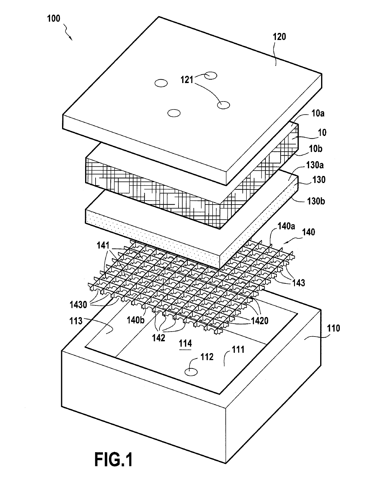
[0034]The method in accordance with the present invention for fabricating a composite material, in particular of the oxide / oxide or CMC type, begins by making a fiber texture that is to form the reinforcement of the part.

[0035]In known manner, the fiber structure is made by weaving using a Jacquard type loom having a bundle of warp yarns or strands arranged in a plurality of layers, the warp yarns being interlinked by weft yarns, or vice versa. The fiber texture may be made by stacking plies obtained by two-dimensional (2D) weaving. The fiber texture may also be made directly as a single part by three-dimensional (3D) weaving. The term “two-dimensional weaving” is used herein to mean a conventional weaving technique in which each weft yarn passes from one side to the other of the yarns in a single layer of warp yarns, or vice versa. The method of the invention is particularly suitable for enabling a filled slurry to be introduced into 2D fiber textures, i.e. textures obtained by sta...


PUM

PropertyMeasurementUnit
diameteraaaaaaaaaa
thicknessaaaaaaaaaa
diameteraaaaaaaaaa

Abstract

A method of fabricating a composite material part includes placing a fiber texture in a mold including in its bottom portion a porous material part on which a first face of the texture rests, injecting a liquid under pressure into the fiber texture, the liquid containing a powder of refractory ceramic particles, and draining through the porous material part the liquid that has passed through the fiber texture, while retaining the powder of refractory ceramic particles inside said texture by the porous material part. A perforated rigid element is interposed between the bottom of the mold and the porous material part.

Description

BACKGROUND OF THE INVENTION[0001]The present invention relates to a method of fabricating a thermostructural part out of composite material, in particular material of the oxide / oxide or ceramic matrix composite (CMC) type, i.e. comprising fiber reinforcement made from refractory ceramic material fibers densified by a matrix that is likewise made of refractory ceramic material.[0002]Parts made of oxide / oxide composite material are generally prepared by draping in a mold a plurality of fiber plies made from refractory oxide fibers, with each ply being previously impregnated with a slurry filled with refractory oxide particles. The set of plies as arranged in this way is then compacted by a mold cover or by a vacuum bag and by passing via an autoclave. The resulting filled preform is then subjected to sintering or to ceramization heat treatment in order to form a refractory oxide matrix in the preform and obtain an oxide / oxide composite material part. That technique can also be used fo...

Claims


Application Information

Patent Timeline
Patent Type & Authority Applications(United States)
IPC IPC(8): B28B23/00B28B1/24C04B35/80F01D5/28
CPCB28B23/0006B28B1/24C04B35/80F01D5/282F01D5/284C04B35/622C04B2235/5224C04B2235/5228C04B2235/5232C04B2235/5244C04B2235/5248C04B2235/5256C04B2235/5436C04B2235/602C04B2235/616F05D2230/21F05D2230/40F05D2300/6033F05D2300/6034B01D29/05B28B7/368B28B7/46C04B35/117C04B35/14C04B35/18C04B35/185C04B35/447C04B35/488C04B35/56C04B35/565C04B35/58C04B35/5805C04B35/58071C04B35/584C04B35/6263C04B35/6264B01D2201/0423C04B2235/5252B01D29/822B28B19/00D03D1/0088D03D11/00D10B2401/16B28B1/265C04B35/62844C04B41/4584B28B1/261B28B7/344
Inventor PODGORSKI, MICHAELDAMBRINE, BRUNORUIZ, EDU
Owner SAFRAN
Why Eureka
Try Eureka