Rx delay line inteferometer tracking in closed-loop module control for communication

a delay line and module control technology, applied in the field of communication systems and methods, can solve the problems of large bandwidth requirements of internet and mobile applications, limited popular applications, and small amount of data transferred

Active Publication Date: 2019-06-25
MARVELL ASIA PTE LTD
View PDF6 Cites 4 Cited by
  • Summary
  • Abstract
  • Description
  • Claims
  • Application Information

AI Technical Summary

Benefits of technology

[0014]Embodiments of the present invention can be implemented in conjunction with existing systems and processes. For example, the back-channel data can be implemented to be compatible with existing communication protocols and specifically be used for the near-end receiver to communicate with far-end transmitter for conducting the DLI control loop and the BER-based wavelength control loop in a coordinated manner. Back-channel data are used by optical transceivers that are preconfigured to use them, and optical transceivers that are not configured to use the back-channel data may simply ignore them. In addition, optical transceivers according to embodiments of the present invention can be manufactured using existing manufacturing equipment and techniques. In certain implementations, existing optical transceivers can be upgraded (e.g., through firmware update) to take advantage of the present invention. There are other benefits as well.
[0015]The present invention achieves these benefits and others in the context of known technology. However, a further understanding of the nature and advantages of the present invention may be realized by reference to the latter portions of the specification and attached drawings.

Problems solved by technology

In the early days of the Internet, popular applications were limited to emails, bulletin board, and mostly informational and text-based web page surfing, and the amount of data transferred was usually relatively small.
Today, Internet and mobile applications demand a huge amount of bandwidth for transferring photo, video, music, and other multimedia files.
Unfortunately, existing techniques are inadequate for reasons explained below.

Method used


Image

  • Rx delay line inteferometer tracking in closed-loop module control for communication
  • Rx delay line inteferometer tracking in closed-loop module control for communication
  • Rx delay line inteferometer tracking in closed-loop module control for communication

Examples


Embodiment Construction

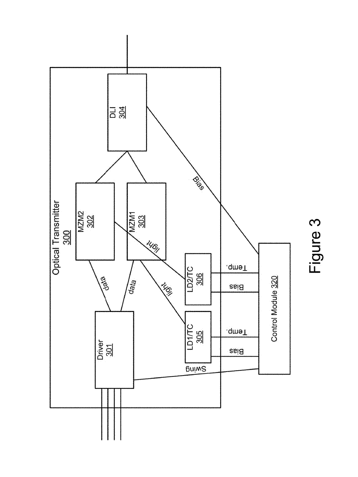
[0026]The present invention is directed to communication systems and methods. According to an embodiment, delay line interferometers (DLIs) in a receiver module of an optical transceiver are configured with a control loop to optimize overall bit-error-rate (BER) of communication signals against any drift. The DLI control is further coordinated with active BER-based wavelength control in a transmitter module of the optical transceiver, both being operated alternatively in time or frequency. There are other embodiments as well.

[0027]Most optical communication modules have some form of internal control systems to maintain the optical performance. For example, typical control parameters include optical power, wavelength, extinction ratio, and / or others. However, in most cases, conventional techniques for the transmitting optical module to maintain these parameters rely on proxy measurements. For example, transmitted optical power may be measured by a tap and photodiode, or extinction ra...


PUM


Abstract

The present invention is directed to a communication signal tracking system comprising an optical receiver including one or more delay line interferometers (DLIs) configured to demultiplex incoming optical signals and a transimpedance amplifier configured to convert the incoming optical signals to incoming electrical signals. The communication signal tracking system further includes a control module configured to calculate a bit-error-rate (BER) of the incoming electrical signals before forward-error correction decoding, and use the BER as a parameter for optimizing settings of the one or more DLIs in one or more iterations in a control loop and generating a back-channel data.

Description

CROSS-REFERENCES TO RELATED APPLICATIONS[0001]NOT APPLICABLE[0002]NOT APPLICABLE[0003]NOT APPLICABLEBACKGROUND OF THE INVENTION[0004]The present invention is directed to communication systems and methods.[0005]Over the last few decades, the use of communication networks exploded. In the early days of the Internet, popular applications were limited to emails, bulletin board, and mostly informational and text-based web page surfing, and the amount of data transferred was usually relatively small. Today, Internet and mobile applications demand a huge amount of bandwidth for transferring photo, video, music, and other multimedia files. For example, a social network like Facebook processes more than 500 TB of data daily. To move a large amount of data, optical communication networks are often used.[0006]With high demand for communication networks came high demand for quality networking devices. In high-speed communication systems, having optimized optical transceivers can meaningfully im...

Claims


Application Information

Patent Timeline
Patent Type & Authority Patents(United States)
IPC IPC(8): H04B10/69H04B10/61H04B10/67H04L27/18G02B6/12G02B6/293H04B17/20H04L27/06
CPCH04B10/614G02B6/12007G02B6/29347H04B10/69H04B17/20H04L27/18H04B10/677H04L27/06H04B10/40H04B10/66H04B10/697H04L1/004H04B10/07953H04B10/675
Inventor ROPE, TODDCHOI, SUNGSTEWART, JAMESNAGARAJAN, RADHAKRISHNAN L.YU, PAULLYUBOMIRSKY, ILYA
Owner MARVELL ASIA PTE LTD
Why Eureka
Try Eureka