Calibration device and uses thereof
a technology of a calibration device and a polarization axis, which is applied in the direction of instruments, color/spectral property measurement, polarisation-affecting properties, etc., can solve the problems of inaccurate preparation, degradation over time, and limited number or range of wavelengths
- Summary
- Abstract
- Description
- Claims
- Application Information
AI Technical Summary
Benefits of technology
Problems solved by technology
Method used
Image
Examples
example 1
Optical Device for Calibrating Circular or Linear Dichroism Spectrometers
[0174]Several optical CD calibration devices have been described in the literature, however these suffer from certain drawbacks which the present invention overcomes. One device (L. A. Nafie, T. A. Kiederling and P. J. Stevens, “Vibrational Circular Dichroism”, Jour. Am. Chem. Soc., 98(10), 2715 (1975)) consists of a birefringent sapphire plate (a waveplate) and a linear polarizer and is designed for calibration of VCD (i.e. infra-red CD) spectrometers. Such a device is not applicable to the UV-VIS region for two reasons: 1) The signal produced is much too large (˜30,000 mdeg) and is well outside the range of typical UV-VIS CD measurements. Such a signal would saturate the AC electronics channel in a UV-VIS CD instrument. 2) There is no suitable polarizer (one which completely blocks the unwanted polarization state) which would cover the full range of a UV instrument (170 nm to 1000 nm+). Hence use of this devi...
example 2
Specifications
[0233]The design of the production version of DichOS requires a careful consideration of the waveplate specification, in particular with respect to the following design requirements:
[0234]A reasonable number of peaks across the entire spectral region (170 nm to 1000 nm+) are required, without the peak density becoming so great in the UV that the peak width approaches a typical spectral bandwidth setting for CD measurement (˜1 nm). It is useful to have a peak somewhere in the region 1000 nm to 1700 nm to provide a high calibration point for extended wavelength range CD instruments.
[0235]Thin, low order waveplates are preferable because that they have lower temperature dependence and wider acceptance angles. However, the waveplate should not be so thin that structural integrity, fragility and fabrication difficulties become an issue.
[0236]It is highly desirable that some of the peaks in the DichOS spectrum correspond closely with known strong lines from standard calibrat...
example 3
tion Variants and Correction for Beam Incidence and Divergence Errors
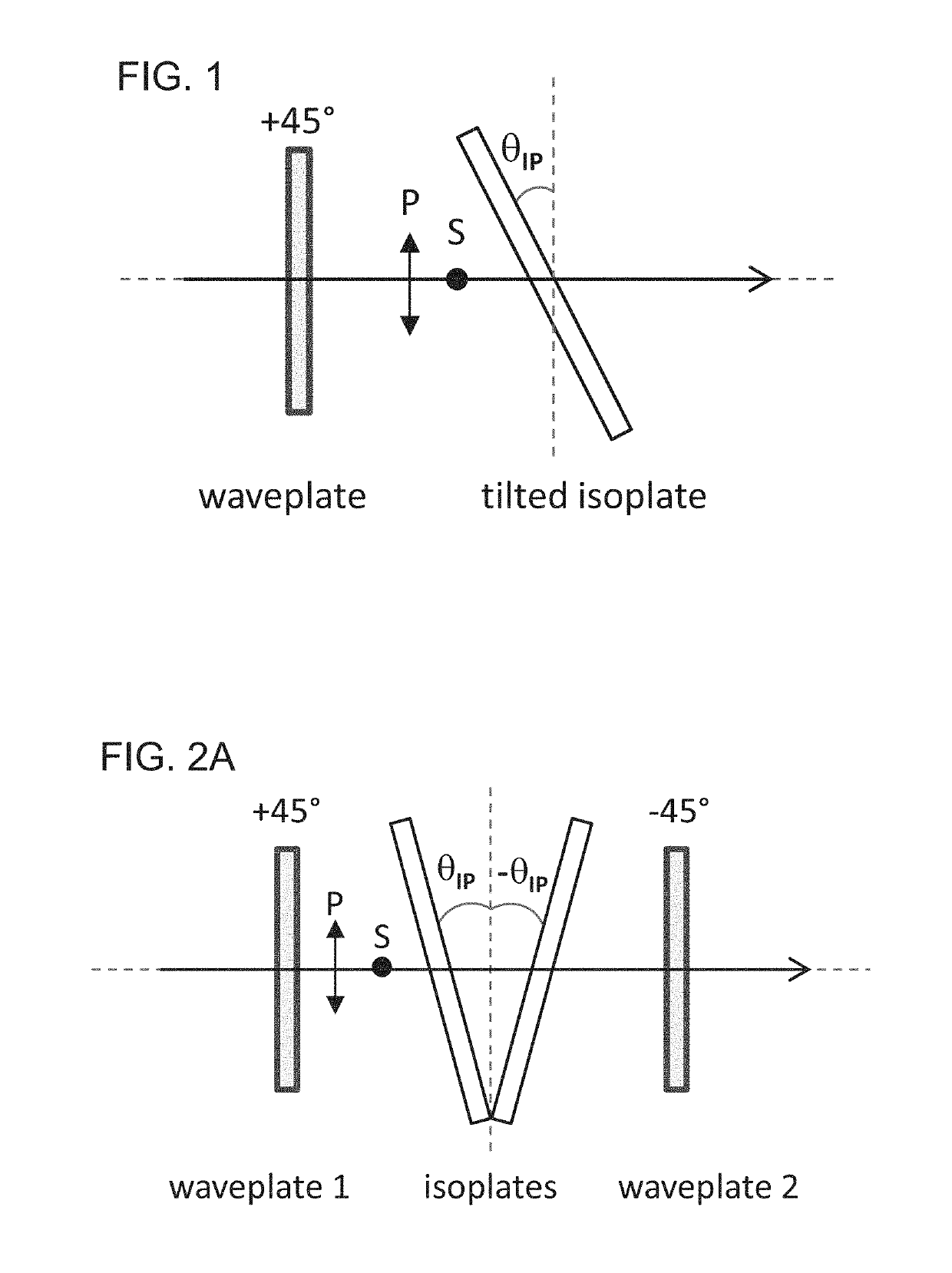
[0259]The next set of experiments describes the optimization of the optical device, termed herein as “DichOS.”
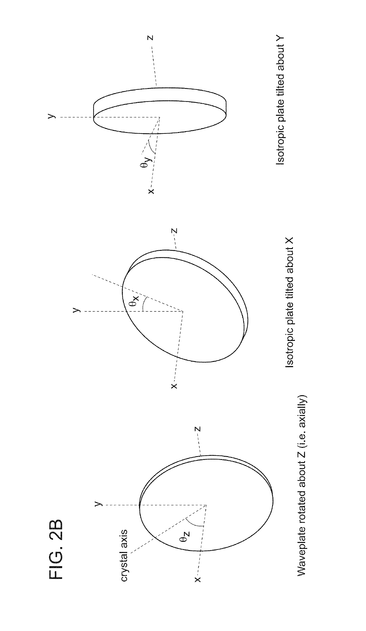
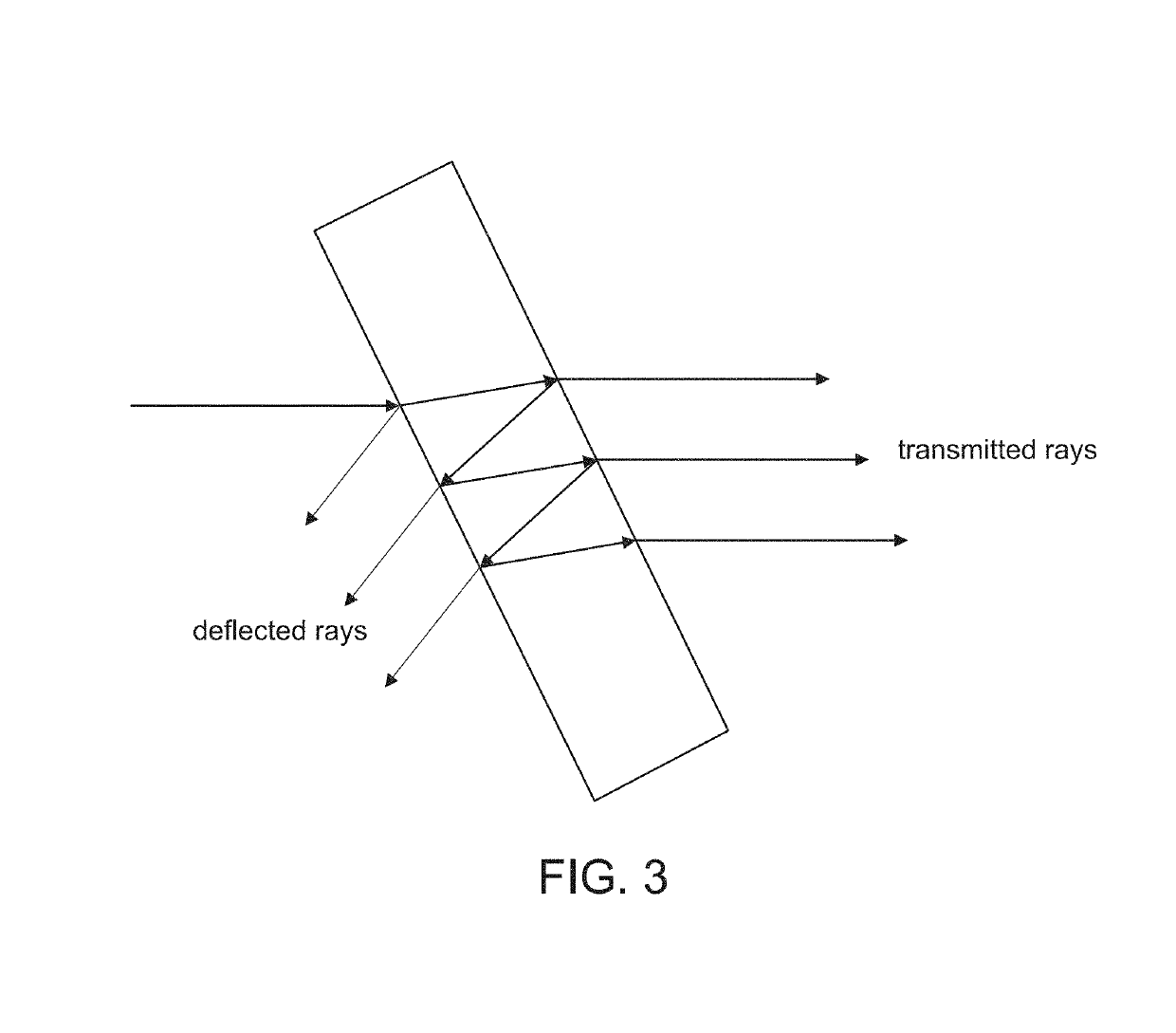
[0260]The studies described herein were, in part, aimed at finding ways to reduce the errors associated with beam incidence angle and beam divergence (henceforth referred to as “beam errors”). As discussed supra, these errors can be problematic for the viability of the device because, being dependent on the characteristics of the instrument measuring beam, they cannot be controlled directly via tolerancing or metrology during manufacture of the DichOS standard itself. Instead, methods are preferred which either enable subtraction of these errors, or which render the device less sensitive to beam incidence angle and divergence. These improved devices are much less sensitive to beam angular errors and divergence, and much less sensitive to detector polarization bias (as seen with photomultipliers). Exemplary ...
PUM
| Property | Measurement | Unit |
|---|---|---|
| thickness | aaaaa | aaaaa |
| angle | aaaaa | aaaaa |
| angle | aaaaa | aaaaa |
Abstract
Description
Claims
Application Information
 - R&D
- Intellectual Property
- Life Sciences
- Materials
- Tech Scout
- Unparalleled Data Quality
- Higher Quality Content
- 60% Fewer Hallucinations
Browse by: Latest US Patents, China's latest patents, Technical Efficacy Thesaurus, Application Domain, Technology Topic, Popular Technical Reports.
© 2025 PatSnap. All rights reserved.Legal|Privacy policy|Modern Slavery Act Transparency Statement|Sitemap|About US| Contact US: help@patsnap.com


