Dust collection device

a technology for collecting devices and dust, which is applied in the direction of vapor flow control, chemistry apparatuses and processes, electrical supply techniques, etc., can solve the problems of lack of operation reliability of the collection device, achieve the effect of preventing a decrease in oxygen eliminating unwanted contaminants, water vapor, and odors in the room space, and facilitating maintenan

Active Publication Date: 2019-07-23
CREATIVE TECH CORP
View PDF54 Cites 7 Cited by
  • Summary
  • Abstract
  • Description
  • Claims
  • Application Information

AI Technical Summary

Benefits of technology

[0033]As described in detail hereinbefore, since the dust collection device of the present invention is structured to collect dust by suctioning air containing the dust in a surface direction of the dust collection device, so that an excellent effect of installing the dust collection device in accordance with a window, etc., in a room is obtained. As a result, by fitting a plurality of dust collection devices to a plurality of windows provided in a room as an enclosed space, an effect of cleaning air in the space while ventilating it is obtained. Since fresh air is supplied into the room space, an effect of securing fresh oxygen in the room space and preventing a decrease in oxygen in the room space is obtained. In addition, unwanted contaminants, water vapor, and odors in a room space can be eliminated.
[0034]Further, the entire dust collection device can be formed into a sheet shape that is lightweight and thin, and does not require a large space, so that an effect of easily performing maintenance such as washing is obtained.
[0035]In addition, since the first electrode exposed inside the first ventilation hole and the second electrode exposed inside the second ventilation hole are disposed to deviate by a predetermined distance from each other, so that an effect of preventing spark discharge between these electrodes is obtained.
[0036]Since the device does not need an ionization unit that has a complicated structure and easily malfunctions, an effect of providing a downsized and thin dust collection device that has high operation reliability and includes a small number of components is obtained.
[0037]The invention of the second aspect brings about an effect of improving dust attraction capacity of the device.
[0038]The invention of the third and fourth aspects brings about an effect of not only improving the capacity of the device for electrically charging dust but also reliably eliminating dust with a large diameter.

Problems solved by technology

However, in this dust collection device, an ionization unit that has a complicated structure and easily malfunctions must be provided in a preceding stage of the dust collection unit, so that the dust collection device lacks operation reliability.

Method used


Image

  • Dust collection device
  • Dust collection device
  • Dust collection device

Examples


first embodiment

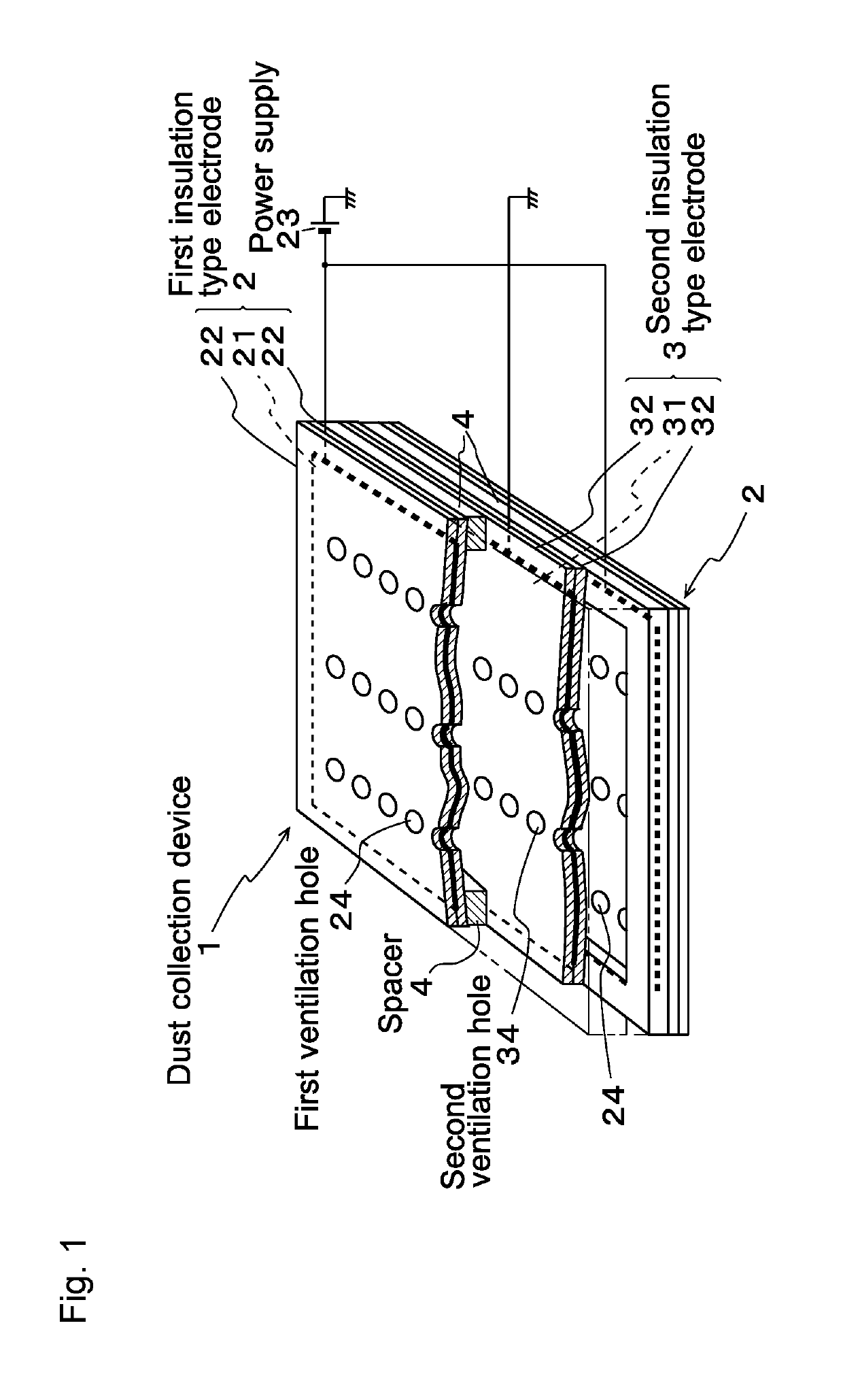
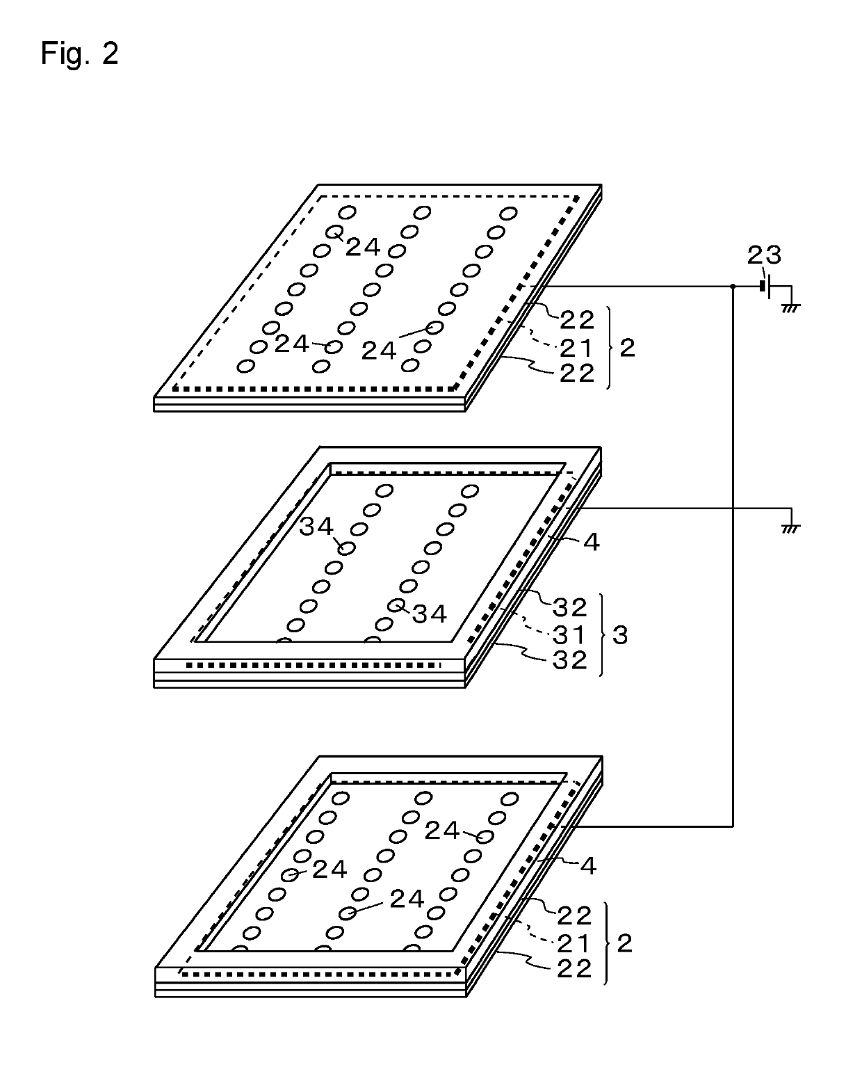
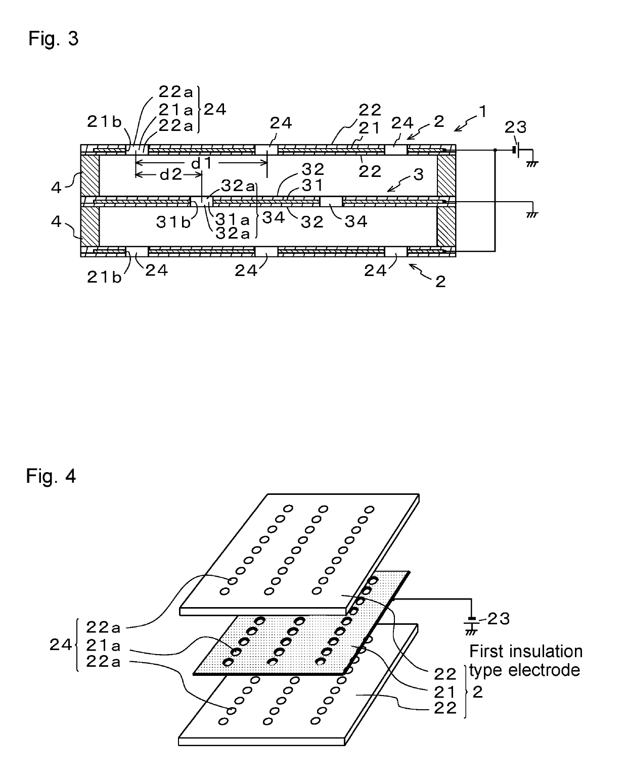
[0059]FIG. 1 is a partially cutaway perspective view of a dust collection device according to a first embodiment of the present invention. FIG. 2 is an exploded perspective view of the dust collection device according to the first embodiment. FIG. 3 is a sectional view of the dust collection device.

[0060]As shown in FIG. 1, the dust collection device 1 is structured by laminating first insulation type electrodes 2 and a second insulation type electrode 3 alternately via insulating spacers 4.

[0061]Specifically, in this embodiment, as shown in FIG. 2, two first insulation type electrodes 2 and one second insulation type electrode 3 are laminated alternately. In this case, by interposing a spacer 4 having a quadrilateral frame shape between the second insulation type electrode 3 and the upper first insulation type electrode 2, and interposing a similar spacer 4 between the second insulation type electrode 3 and the lower first insulation type electrode 2, a space corresponding to a thi...

second embodiment

[0093]Next, a second embodiment of the present invention is described.

[0094]FIG. 8 is a sectional view showing a dust collection device according to a second embodiment of the present invention. FIG. 9 are plan views of insulation type electrodes, FIG. 9(a) shows a first insulation type electrode 2, and FIG. 9(b) shows a second insulation type electrode 3. FIG. 10 is a partial enlarged view of the first and second ventilation holes 24 and 34.

[0095]As shown in FIG. 8, in the dust collection device 1 of this embodiment, structures of the first and second ventilation holes 24 and 34 of the first and second insulation type electrodes 2 and 3 are different from those of the first embodiment.

[0096]Specifically, in the first ventilation hole 24 of each first insulation type electrode 2, a bore diameter of the hole 22a′ of the upper first insulating layer 22 in the drawing is set to be larger than a bore diameter of the hole 21a of the first electrode 21 and a bore diameter of the hole 22a ...

third embodiment

[0103]Next, a third embodiment of the present invention is described.

[0104]FIG. 11 is a sectional view showing a dust collection device according to a third embodiment of the present invention. FIG. 12 are plan views of insulation type electrodes, FIG. 12(a) shows a first insulation type electrode 2 and FIG. 12(b) shows a second insulation type electrode 3. FIG. 13 is a partial enlarged view of first and second ventilation holes 24 and 34.

[0105]As shown in FIG. 11, in the dust collection device 1 of this embodiment, structures of the first and second electrodes 21 and 31 exposed inside the first and second ventilation holes 24 and 34 of the first and second insulation type electrodes 2 and 3 are different from those in the first and second embodiments described above.

[0106]Specifically, a part of the first electrode 21 is exposed inside the first ventilation hole 24 of the first insulation type electrode 2, and this exposed portion 21d is formed of conductive fibers directed toward ...


PUM


Abstract

A dust collection device can be fitted to windows in a room, thus not only cleaning air while ventilating air within a space targeted for cleaning but also cleaning air outside of the space. A dust collection device is constructed by laminating first insulation type electrodes and second insulation type electrodes alternately via spacers. The insulation type electrodes have a configuration in which both sides of first electrodes (second electrodes) are coated by first insulating layers (second insulating layers). Furthermore, a power supply is connected to the electrodes, and the electrodes are grounded. In addition, a plurality of first through holes (second through holes) is provided in rows in the insulation type electrodes. Furthermore, the positions of the through holes in the insulation type electrodes are arranged in a plane view so as to be a prescribed distance from the positions of the through holes in the insulation type electrodes.

Description

TECHNICAL FIELD[0001]The present invention relates to a dust collection device to eliminate dust in a gaseous body such as air.BACKGROUND ART[0002]Conventionally, as a dust collection device of this kind, for example, a technology is described in Patent Literature 1.[0003]This dust collection device is a technology in which, after dust is electrically charged by discharge in an ionization unit in a preceding stage, an electric field is formed by alternately applying different voltages to laminated electrode plates in a dust collection unit in a subsequent stage, and the dust electrically charged in the ionization unit is collected by this dust collection unit.[0004]However, in this dust collection device, an ionization unit that has a complicated structure and easily malfunctions must be provided in a preceding stage of the dust collection unit, so that the dust collection device lacks operation reliability.[0005]Therefore, like the technology described in Patent Literature 2, a dus...

Claims


Application Information

Patent Timeline
Patent Type & Authority Patents(United States)
IPC IPC(8): B03C3/36B03C3/70B03C3/41B03C3/47B03C3/09B03C3/38
CPCB03C3/366B03C3/09B03C3/70B03C3/41B03C3/47B03C3/38B03C3/68B03C3/64B03C3/36B03C3/40
Inventor LUO, LI
Owner CREATIVE TECH CORP
Why Eureka
Try Eureka