
Hybrid flow control method for simple hinged flap high-lift system

a high-lift system and hinged flap technology, applied in the field of hybrid flow control methods for simple hinged flap high-lift systems, can solve the problems of sacrificing cruise efficiency and acoustic performance, complex high-lift systems for low-speed flight conditions, and slotted leading and trailing edge devices, etc., to achieve equivalent flow control performance, reduce mass flow, differential pressure and power requirements, and reduce the power requirement of afc

Inactive Publication Date: 2019-07-23
NASA
View PDF8 Cites 4 Cited by
  • Summary
  • Abstract
  • Description
  • Claims
  • Application Information

AI Technical Summary

Benefits of technology

The hybrid flow control system for a hinged flap high-lift system uses both active and passive flow control techniques to reduce the amount of mass flow, differential pressure, and power needed for equivalent performance. This system achieves the necessary lift enhancement for high-lift applications while keeping the pneumatic power requirement within an aircraft's capability. Overall, this system provides a more efficient and effective solution for high-lift applications.

Problems solved by technology

Current high-lift systems for low-speed flight conditions are complex systems in which cruise efficiency and acoustic performance are sacrificed during takeoff and landing operations.
The slotted leading and trailing edge devices, and the associated sub-systems necessary to change the wing configuration from cruise to low-speed conditions, are complex and employ a significant number of parts to enable safe operation.
In addition, these complex mechanical high-lift systems (e.g., Fowler flap mechanisms) often protrude externally under the wings, and thus often require external fairings, that result in increased cruise drag.
However, simple hinged flaps are currently not used in high-lift systems of transport aircraft because simple hinged flaps are vulnerable to flow separation at high flap deflections for both trailing edge and leading edge applications.

Method used


Image

  • Hybrid flow control method for simple hinged flap high-lift system
  • Hybrid flow control method for simple hinged flap high-lift system
  • Hybrid flow control method for simple hinged flap high-lift system

Examples


Embodiment Construction

[0014]For purposes of description herein, it is to be understood that the specific devices and processes illustrated in the attached drawings, and described in the following specification, are simply exemplary embodiments of the inventive concepts defined in the appended claims. Hence, specific dimensions and other physical characteristics relating to the embodiments disclosed herein are not to be considered as limiting, unless the claims expressly state otherwise.

[0015]The word “exemplary” is used herein to mean “serving as an example, instance, or illustration.” Any implementation described herein as “exemplary” is not necessarily to be construed as preferred or advantageous over other implementations.

[0016]The various embodiments will be described in detail with reference to the accompanying drawings. Wherever possible, the same reference numbers will be used throughout the drawings to refer to the same or like parts. References made to particular examples and implementations are...


PUM


Abstract

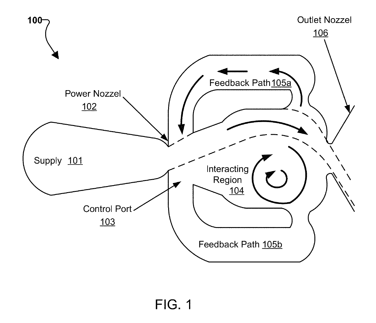
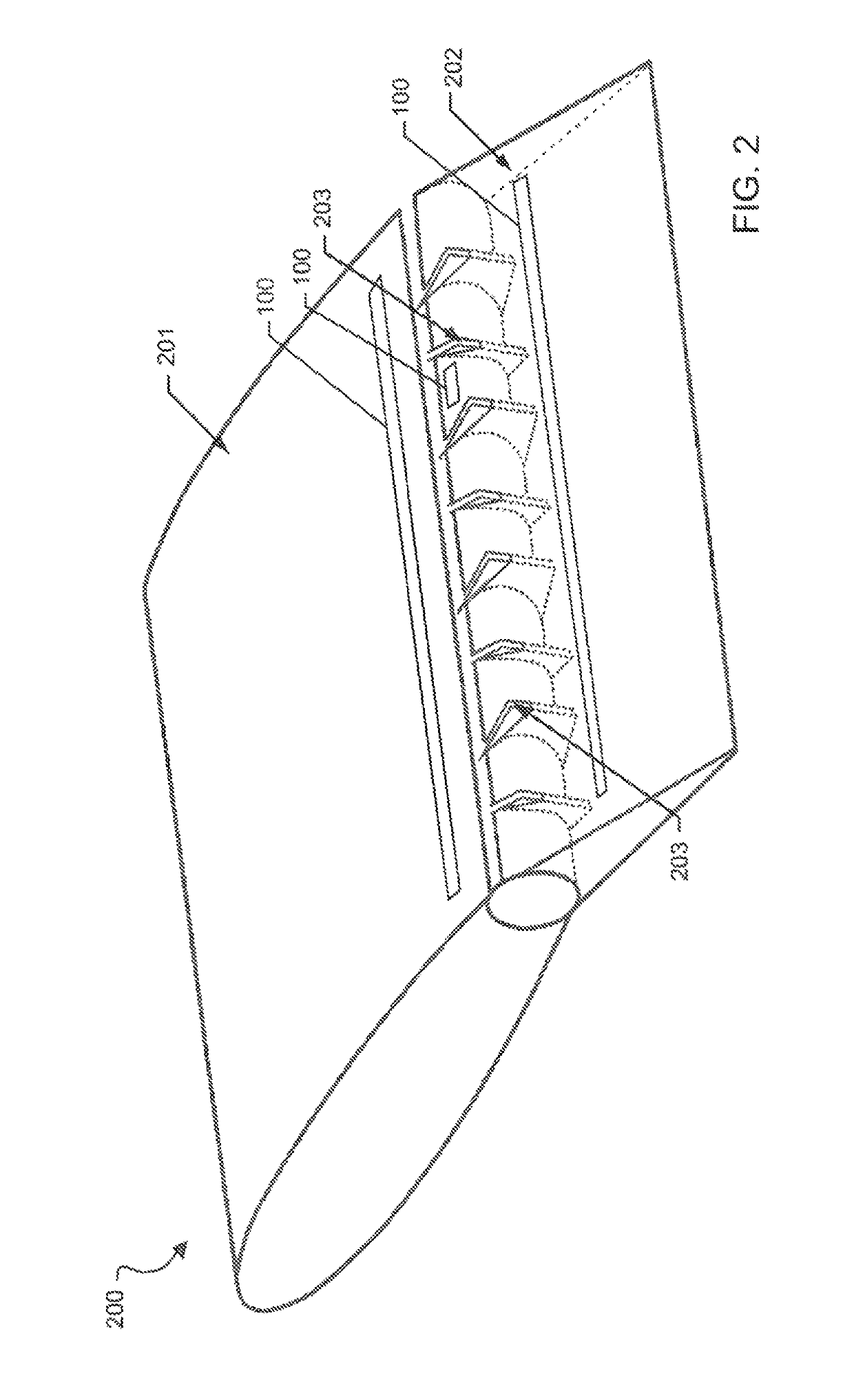
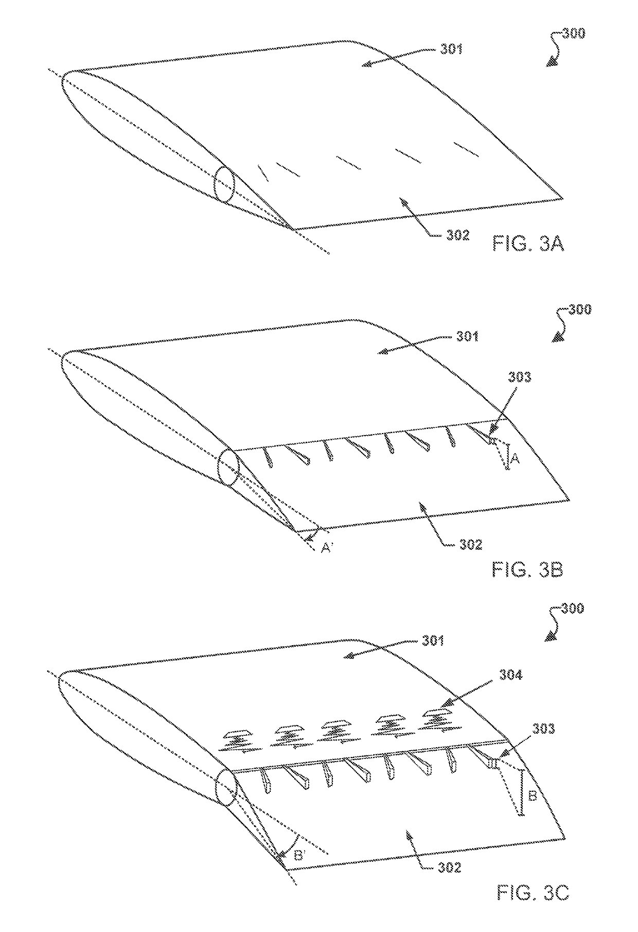
Systems, methods, and devices are provided that provide hybrid flow control for a simple hinged flap high-lift system using sweeping jet (SWJ) actuators for active flow control (AFC) and adaptive vortex generators (AVGs) that may be actuated by flap deflection for passive flow control (PFC). The various embodiments may significantly reduce mass flow, differential pressure, and power requirements for equivalent flow control performance when compared to using AFC only. The various embodiments may reduce the power requirement of AFC, while still maintaining the aerodynamic performance enhancement necessary for high-lift applications using a simple hinged flap. The various embodiments may provide the necessary lift enhancement for a simple hinged flap high-lift system, while keeping the pneumatic power requirement (mass flow and pressure) for the AFC within an aircraft's capability for system integration.

Description

CROSS-REFERENCE TO RELATED PATENT APPLICATIONS[0001]This patent application claims the benefit of and priority to U.S. Provisional Patent Application No. 62 / 085,678 entitled “Hybrid Flow Control Method for Simple Hinged Flap High-Lift System” filed on Dec. 1, 2014 and U.S. Provisional Patent Application No. 62 / 156,507 entitled “Hybrid Flow Control Method for Simple Hinged Flap High-Lift System” filed on May 4, 2015. The entire contents of both applications are hereby incorporated by reference in their entirety.STATEMENT REGARDING FEDERALLY SPONSORED RESEARCH OR DEVELOPMENT[0002]The invention described herein was made by employees of the United States Government and may be manufactured and used by or for the Government of the United States of America for governmental purposes without the payment of any royalties thereon or therefore.BACKGROUND OF THE INVENTION[0003]High-lift systems are designed to allow a transport aircraft—with typical transonic cruise speeds—to safely operate at l...

Claims


Application Information

Patent Timeline
Patent Type & Authority Patents(United States)
IPC IPC(8): B64C23/06B64C21/08B64C9/16B64C3/50B64C21/04
CPCB64C23/06B64C3/50B64C9/16B64C21/04B64C21/08Y02T50/44Y02T50/14Y02T50/162Y02T50/166Y02T50/32Y02T50/10Y02T50/30Y02T50/40
Inventor LIN, JOHN C.KOKLU, MEHTI
Owner NASA
Learn More