Communication system
a communication system and communication system technology, applied in the field of communication systems, can solve problems such as collision risks, and achieve the effects of reducing the power consumption of narrow-bandwidth terminal devices, reducing the structure of communication systems, and reducing the risk of collisions
- Summary
- Abstract
- Description
- Claims
- Application Information
AI Technical Summary
Benefits of technology
Problems solved by technology
Method used
Image
Examples
first embodiment
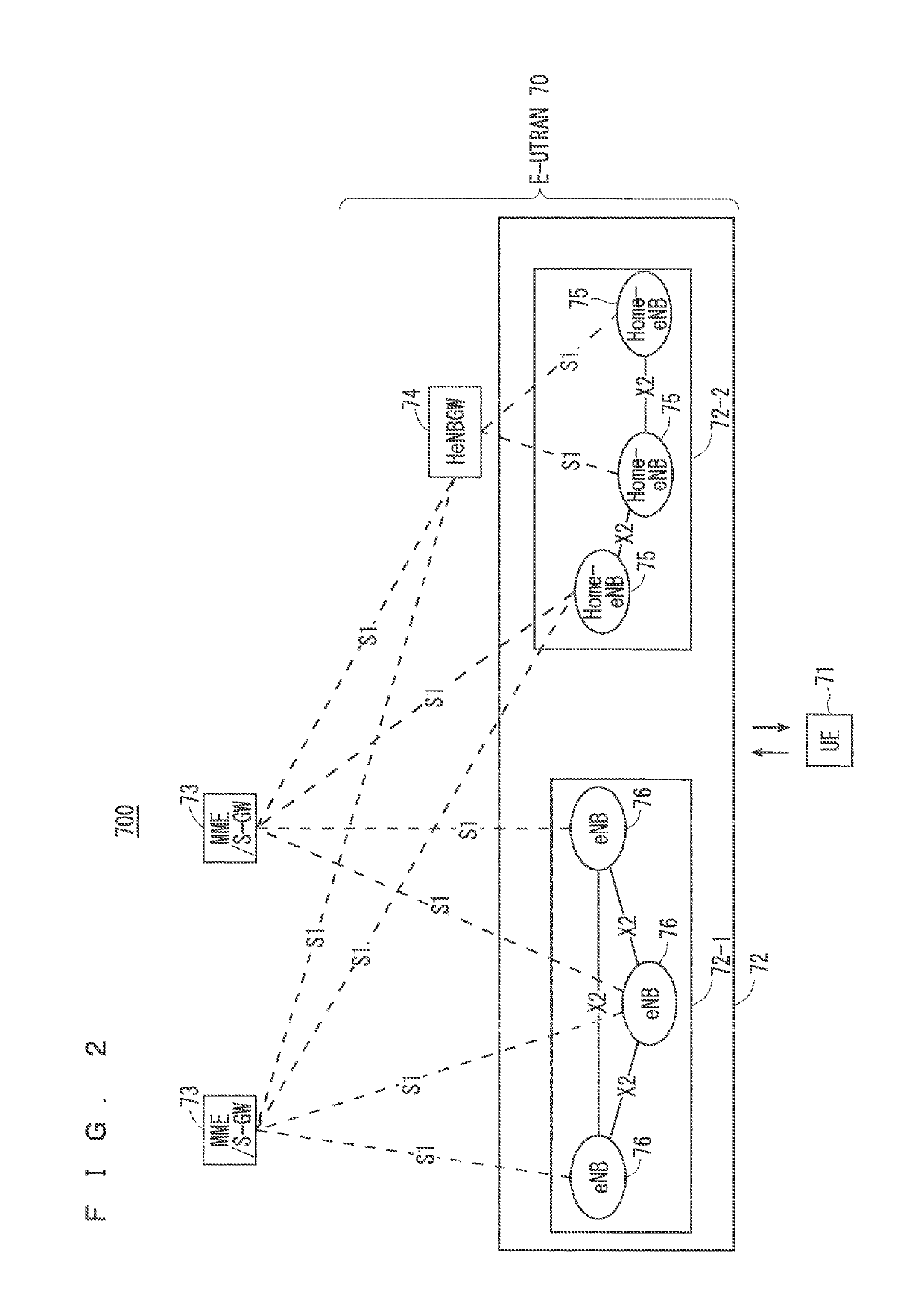
[0099]FIG. 2 is a block diagram showing an overall configuration of an LTE communication system 700, which is under discussion of 3GPP. FIG. 2 will be described. A radio access network is referred to as an evolved universal terrestrial radio access network (E-UTRAN) 70. A user equipment device (hereinafter, referred to as a “user equipment (UE)”) 71 that is a communication terminal device is capable of radio communication with a base station device (hereinafter, referred to as a “base station (E-UTRAN Node B: eNB)”) 72 and transmits and receives signals through radio communication.
[0100]The E-UTRAN is composed of one or a plurality of base stations 72, provided that a control protocol for a user equipment 71 such as a radio resource control (RRC), and user planes such as a packet data convergence protocol (PDCP), radio link control (RLC), medium access control (MAC), or physical layer (PHY) are terminated in the base station 72.
[0101]The control protocol radio resource control (RRC)...
second embodiment
[0298]The LC-MTC UE may select a far cell depending on a radio environment in the cell selection process. As described in the first embodiment, when the SI for reselecting a cell is reduced to meet the demand for reduction in the SI of the LC-MTC UE, unless something is done, the cell reselection process of the LC-MTC UE is not performed.
[0299]Here, until the next cell selection process is performed, it is necessary to camp on the far cell that has been temporarily selected. Accordingly, it is highly probable that the reception quality in the LC-MTC UE is degraded and the LC-MTC UE moves out of the coverage area. When moving out of the coverage area, the LC-MTC UE newly performs a cell selection process according to an instruction of the NAS, establishes the RRC connection, and performs an attach process or the TAU process. Accordingly, a problem with increase in power consumption of the LC-MTC UE occurs.
[0300]The cell selection process has a stored information cell selection functi...
third embodiment
[0313]The paging repetitions are being studied for LC-MTC requiring coverage enhancement. The repeated transmission improves the reception quality in the LC-MTC UEs in the enhanced coverage areas.
[0314]Since the paging repetitions are not conventionally performed, 3GPP is studying new methods for the paging repetitions. Non-Patent Document 11 discloses a method for repeated paging transmission across subframes as a method for the paging repetitions.
[0315]However, none of the details of the structure of the subframes for paging transmission is disclosed. Thus, it becomes unclear which subframe the LC-MTC UE should receive, and the LC-MTC UE cannot receive pagings including repetitions.
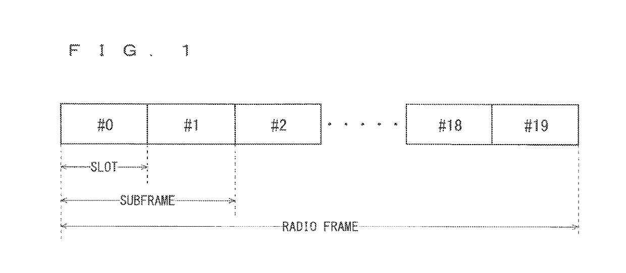
[0316]The third embodiment will disclose a detailed method for the paging repetitions. The paging transmission including the repetitions are performed across radio frames. The transmission may be performed through consecutive radio frames. An initial paging may be transmitted on radio frames and subfram...
PUM
 Abstract
Description
Claims
Application Information
 - R&D
- Intellectual Property
- Life Sciences
- Materials
- Tech Scout
- Unparalleled Data Quality
- Higher Quality Content
- 60% Fewer Hallucinations
Browse by: Latest US Patents, China's latest patents, Technical Efficacy Thesaurus, Application Domain, Technology Topic, Popular Technical Reports.
© 2025 PatSnap. All rights reserved.Legal|Privacy policy|Modern Slavery Act Transparency Statement|Sitemap|About US| Contact US: help@patsnap.com


