
Apparatus and method for monitoring an electric power transmission system through partial discharges analysis

a technology of partial discharge and monitoring apparatus, applied in the direction of measuring device, dielectric strength testing, instruments, etc., can solve the problems of complex and expensive techniques, inaccurate techniques, and inability to accurately measure the power of the transmission system, and achieve the effect of reliable results

Active Publication Date: 2019-07-30
PRYSMIAN SPA
View PDF26 Cites 1 Cited by
  • Summary
  • Abstract
  • Description
  • Claims
  • Application Information

AI Technical Summary

Benefits of technology

The patent text describes a method and device for automatically detecting and assessing partial discharges in an electric power transmission system. The invention uses a number of tests, preferably at least 15, to reliably represent different situations that may affect the evaluation of electric pulses. The technique is simpler and less expensive than existing techniques and can provide accurate results even in the event of anomalous situations.

Problems solved by technology

These techniques are complicated and expensive.
Moreover, however refined they may be, these techniques are still inaccurate because the electric power transmission system under analysis (e.g., the electric conductors, junctions and / or terminations) are susceptible to unpredictable phenomena linked to their structure and function (e.g., possible manufacturing defects, damages occurred during the laying operations, changes of the transmitted current between day and night, between various seasons of the year, between working days and non-working days, sudden changes of the transmitted current due to unforeseen events, and similar) and to the external environment (e.g. possible natural phenomena, road works, and similar), which can alter the results of the probabilistic / statistical analysis.

Method used


Image

  • Apparatus and method for monitoring an electric power transmission system through partial discharges analysis
  • Apparatus and method for monitoring an electric power transmission system through partial discharges analysis
  • Apparatus and method for monitoring an electric power transmission system through partial discharges analysis

Examples


Embodiment Construction

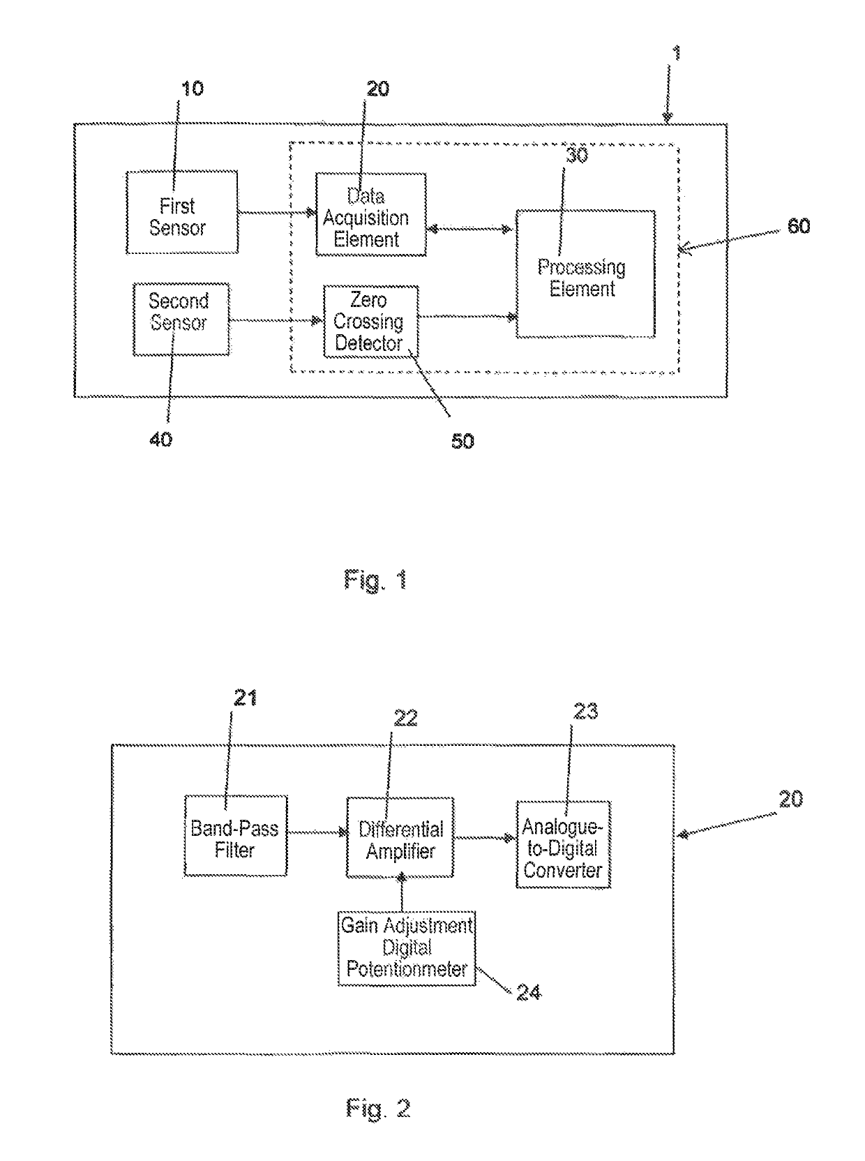
[0076]FIG. 1 shows a block diagram of a partial discharge monitoring apparatus 1 according to an embodiment of the invention, comprising a first sensor 10, a data acquisition element 20, a processing element 30, a second sensor 40, and a zero-crossing detector 50.

[0077]Data acquisition element 20, processing element 30 and zero-crossing detector 50 make part of an acquisition and evaluation module 60.

[0078]The first sensor 10 advantageously is a high frequency (HF) sensor capable of detecting HF analogue electric pulses possibly associated with partial discharges. For example, first sensor 10 can be a conventional inductive sensor, a conventional capacitive sensor, a conventional HFCT (High Frequency Current Transformer), or an antenna acting as electric field detector as disclosed, for example, by WO 2009 / 150627.

[0079]The first sensor 10 advantageously is positioned on a strategic point of an electric power transmission system like, for example, a junction or a termination where pa...


PUM


Abstract

A method for monitoring partial discharges in an electric power transmission system includes the steps of: detecting electric pulses from a component of the electric power transmission system, repeating a battery of different tests adapted to provide each a result indicative of partial discharge activity, the tests being continuously performed in succession one after the other in a preset period of time, each including a set of operations of acquisition and evaluations of the detected electrical pulses, and differing each other for a plurality of different combinations of values taken by test parameters used for executing the acquisition and evaluation operations; analyzing the results obtained with time by the batteries of tests executed at different execution times in the present period of time; and generating an alarm depending on the outcome of the analysis step.

Description

CROSS REFERENCE TO RELATED APPLICATIONS[0001]This application is a national phase application based on PCT / EP2010 / 004561, filed Jul. 26, 2010, the content of all of which is incorporated herein by reference.BACKGROUND OF THE INVENTIONField of the Invention[0002]The present invention relates to an apparatus and method for monitoring an electric power transmission system, in particular a medium / high voltage electric power transmission system, through partial discharges analysis.Description of the Related Art[0003]Electric power transmission from a power generating plant is typically performed by means of medium / high voltage electric power transmission systems that may be aerial (overhead), terrestrial or submarine.[0004]An electric power transmission system can comprise electric conductors (that may be aerial (overhead) conductors, insulated terrestrial conductors or insulated submarine conductors), junctions, terminations and / or insulators for aerial power systems.[0005]A partial dis...

Claims


Application Information

Patent Timeline
IPC IPC(8): G01R31/12
CPCG01R31/1272G01R31/12
Inventor SALES CASALS, LLUIS-RAMONDEL RIO FERNANDEZ, JOAQUINLARA, RAFAELMANUEL LAZARO, ANTONIO
Owner PRYSMIAN SPA
Learn More