Multi-functional underlayment acoustical mat and system

a multi-functional, underlayment technology, applied in resiliently-mounted floors, flooring, synthetic resin layered products, etc., can solve the problems of changing dimensions, leaking water into the cavity with negative consequences, and floor-ceiling systems having less than 55 iics

Active Publication Date: 2019-08-06
UNITED STATES GYPSUM CO
View PDF24 Cites 4 Cited by
  • Summary
  • Abstract
  • Description
  • Claims
  • Application Information

AI Technical Summary

Benefits of technology

[0009]The present multi-functional acoustical underlayment mat meets or exceeds the drawbacks of conventional mats by providing sound isolation, as well as repelling moisture and has a durable surface capable of withstanding trade traffic. When used as a base upon which poured underlayment is applied, moisture from the underlayment slurry is prevented from migrating to the subfloor or related construction. One of the ways in which these goals are achieved is by providing a composite mat having a base or lower layer of entangled polymeric fiber, and an upper layer of sound absorbent, water-repellant nonwoven polymeric fabric which is distinct from the base layer material. The upper layer is preferably a composite of 2 different materials—one of which has dampening characteristics and the upper layer upon which the underlayment is poured, and which has superior moisture and wear resistance. Since the layers are different, each layer has discontinuous acoustic properties, which reduces the amount of sound energy transmitted between the layers, and ultimately, through the floor.

Problems solved by technology

Even though an IIC rating of 50 meets many building codes, experience has shown that in luxury condominium applications floor-ceiling systems having an IIC of less than 55 may not be acceptable because some impact noise is still audible and considered annoying at those levels.
There are concerns that these backings may leak water into the cavity with negative consequences.
One potential issue is that excess water in the poured underlayment slurry prior to setting provides moisture that can encourage the growth of mold and mildew; second is that moisture can affect some materials like nylon and be absorbed by the polymer, causing it to change dimension.
When this dimensional change takes place, the result is often lipping at seams and can cause subsequent cracking issues within the underlayment itself.
Because the backings on current mats in the marketplace tend to be thin, there is little or no contribution to the sound attenuation performance of the sound mat.

Method used


Image

  • Multi-functional underlayment acoustical mat and system
  • Multi-functional underlayment acoustical mat and system

Examples


Embodiment Construction

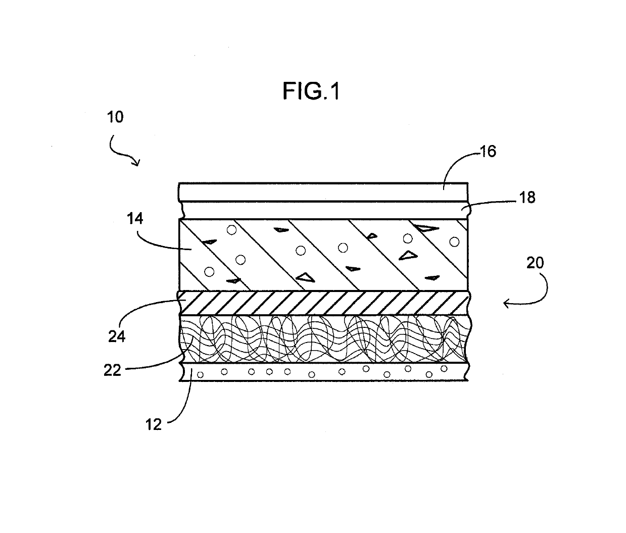
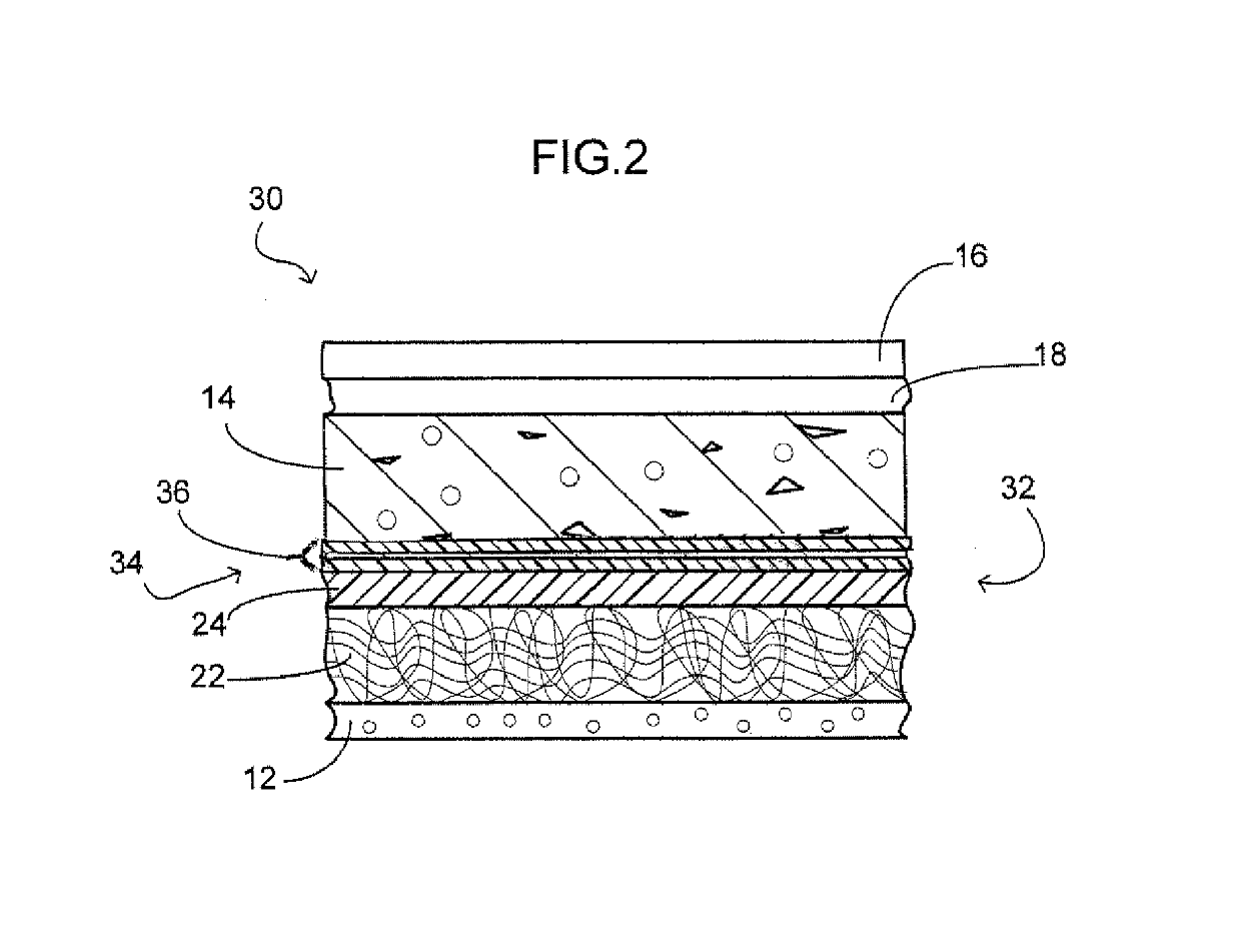
[0014]Referring now to FIG. 1, in which the layers are shown schematically and are not necessarily to scale, the present flooring system is generally designated 10, and is used in a construction having a subfloor 12, shown schematically and typically at least one layer of plywood or Oriented Strand Board (OSB). The subfloor 12 may also be either poured concrete or concrete planks. While only the above two alternatives are disclosed, it is contemplated that any conventional subfloor material will be suitable for use with the present flooring system 10. As is known in the art, the subfloor 12 is supported by framing members (not shown) typically made of wood or steel and available in several configurations, or a poured concrete deck or concrete planks.

[0015]The present flooring system 10 includes a poured underlayment, such as LEVELROCK® floor underlayment, generally designated 14 which is disposed between the subfloor 12 and a finished floor 16 which is typically ceramic tile, vinyl ...


PUM

PropertyMeasurementUnit
heightaaaaaaaaaa
heightaaaaaaaaaa
water resistantaaaaaaaaaa

Abstract

An acoustic isolation mat for placement between a subfloor and a finished floor with a poured underlayment includes a bottom layer of entangled fibers contacting the subfloor; and a top layer attached to the bottom layer and being a water resistant nonwoven polymeric fabric over which the underlayment is poured.

Description

RELATED APPLICATION[0001]This application claims priority pursuant to 35 USC § 119(e) based on U.S. Provisional Patent Application No. 61 / 100,529 Sep. 26, 2008.BACKGROUND OF THE INVENTION[0002]The present invention relates to flooring systems designed to reduce sound transmission, and more specifically relates to an improved nonwoven mat which improves acoustical isolation while avoiding potential moisture retention occurring in some conventional poured underlayment installations.[0003]Conventional flooring systems include a subfloor of poured concrete or plywood. Various combinations of sound mats and underlayments located between the subfloor and the finished floor (typically ceramic tile, vinyl tile or hardwood) have been used to reduce sound transmission.[0004]Sound rated or floating floor systems are known for acoustically isolating a room beneath a floor on which impacts may occur, such as pedestrian footfalls, sports activities, dropping of toys, or scraping caused by moving ...

Claims


Application Information

Patent Timeline
Patent Type & Authority Patents(United States)
IPC IPC(8): E04F15/20B32B27/12B32B5/02
CPCE04F15/20E04F15/203B32B27/12B32B5/022E04B1/86E04F15/10E04F15/18
Inventor SOCHA, DENNIS ALBERT
Owner UNITED STATES GYPSUM CO
Why Eureka
Try Eureka