Gas sensor element

a technology of gas sensor element and sensor element, which is applied in the field of gas sensor element, can solve the problems of reducing the waterproofness of the protective layer, unable to keep the surface roughness ra of the protective layer below or equal to 3.0 m, and disabling the protective layer from being water-repellent at high temperature, so as to improve the resistance of the gas sensor element to water damage and the resistance and suppress the damage of the gas sensor elemen

Active Publication Date: 2019-08-13
DENSO CORP
View PDF3 Cites 0 Cited by
  • Summary
  • Abstract
  • Description
  • Claims
  • Application Information

AI Technical Summary

Benefits of technology

[0008]When the properties of fuel combusted in an internal combustion engine are inferior, the fuel contains many poisoning substances such as Mn, Fe, Ca and the like. Moreover, when these poisoning substances are exhausted along with the exhaust gas and adhere to the protective layer, it may become impossible to keep the surface roughness Ra of the protective layer lower than or equal to 3.0 μm, thereby disabling the protective layer from being water-repellent at high temperature. Consequently, the resistance of the gas sensor element to water damage may be lowered and thus water may intrude into the gas sensor element.
[0022]Moreover, in the above gas sensor element, it is preferable that: the main body further includes a porous diffusion-resistant layer that allows the measurement gas, which is introduced to the measurement gas-side electrode, to permeate therethrough; in the main body, there is formed a gas introduction passage for introducing the measurement gas to the measurement gas-side electrode via the porous diffusion-resistant layer; the gas introduction passage has a main body-side introduction port that opens on the outer peripheral surface of the main body; and the at least one measurement gas introduction port of the protective layer is formed at a position opposite to the main body-side introduction port from the outer side. In this case, it is possible to form the at least one measurement gas introduction port in the vicinity of the main body-side introduction port. Consequently, it is possible to shorten the flow path of the measurement gas from the at least one measurement gas introduction port to the main body-side introduction port, thereby improving the sensitivity of the gas sensor element.

Problems solved by technology

However, the inventors of the present application have found that the gas sensor element disclosed in Patent Document 1 involves the following problems.
When the properties of fuel combusted in an internal combustion engine are inferior, the fuel contains many poisoning substances such as Mn, Fe, Ca and the like.
Moreover, when these poisoning substances are exhausted along with the exhaust gas and adhere to the protective layer, it may become impossible to keep the surface roughness Ra of the protective layer lower than or equal to 3.0 μm, thereby disabling the protective layer from being water-repellent at high temperature.
Consequently, the resistance of the gas sensor element to water damage may be lowered and thus water may intrude into the gas sensor element.
Hence, when the rate of pressure increase due to the vaporization and expansion of the water is high with respect to the speed at which the water vapor permeates through the protective layer and is exhausted, the pressure inside the gas sensor element will become high so that the gas sensor element may be damaged.

Method used


Image

  • Gas sensor element
  • Gas sensor element
  • Gas sensor element

Examples


first embodiment

(First Embodiment)

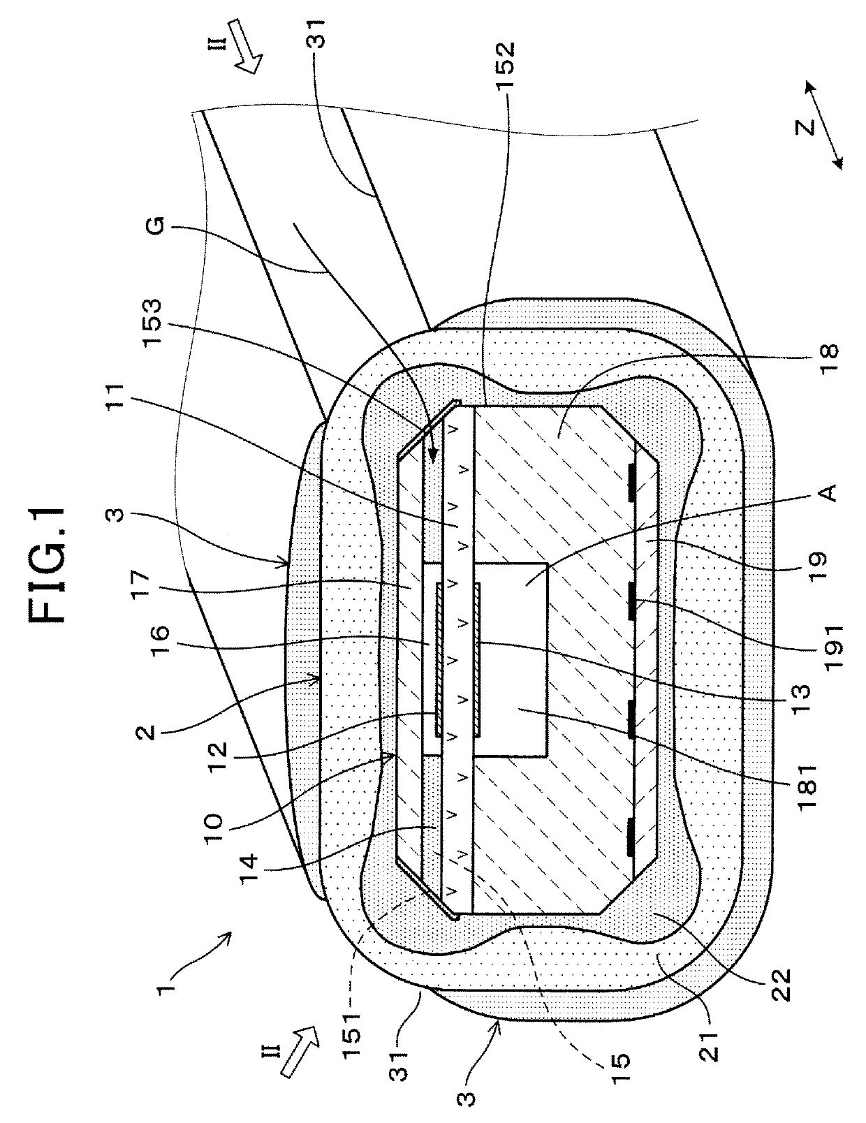
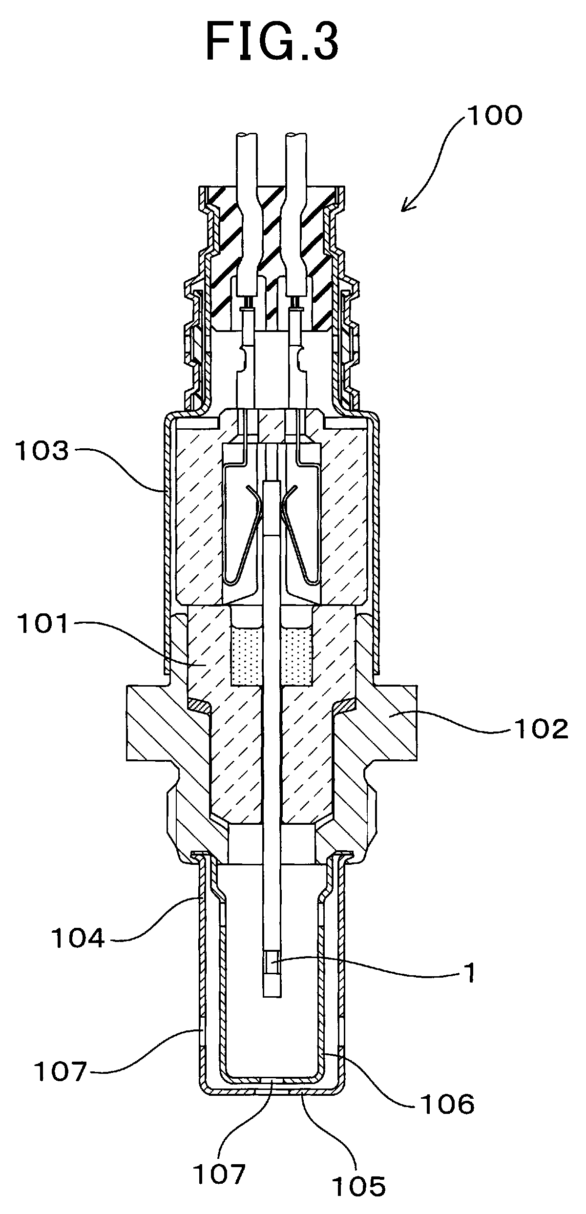
[0030]A gas sensor element 1 according to the first embodiment will be described hereinafter with reference to FIGS. 1-3.

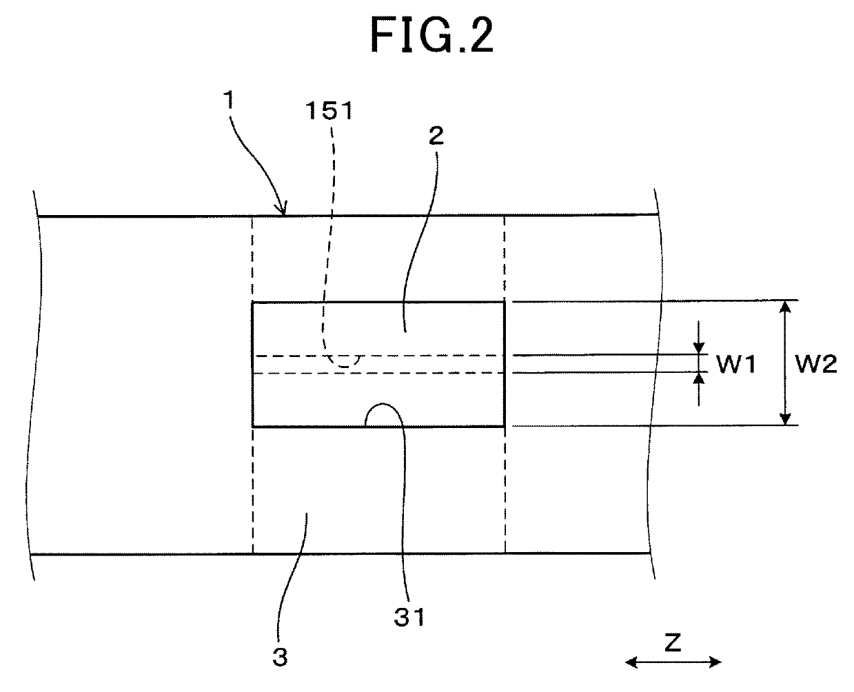
[0031]As shown in FIG. 1, the gas sensor element 1 includes a main body 10, a trap layer 2 covering an outer peripheral surface 152 of the main body 10, and a protective layer 3 covering an outer peripheral surface of the trap layer 2.

[0032]The main body 10 includes a solid electrolyte body 11 having oxygen ion conductivity, a measurement gas-side electrode 12 provided on one surface of the solid electrolyte body 11, a reference gas-side electrode 13 provided on the other surface of the solid electrolyte body 11, and a porous diffusion-resistant layer 14 that allows a measurement gas G, which is introduced to the measurement gas-side electrode 12, to permeate therethrough.

[0033]The trap layer 2 is formed of a porous material that allows the measurement gas G to permeate therethrough. The trap layer 2 is provided to trap poisoning substances conta...

second embodiment

(Second Embodiment)

[0063]In the present embodiment, as shown in FIG. 4, the formation positions of the pair of measurement gas introduction ports 31 of the protective layer 3 in the gas sensor element 1 of the first embodiment are modified. Specifically, in the present embodiment, the measurement gas introduction ports 31 of the protective layer 3 are formed at positions distant from the main body-side introduction ports 151 of the gas introduction passage 15. More specifically, the measurement gas introduction ports 31 are formed at positions respectively opposite to those corners of the main body 10 where no main body-side introduction ports 151 are formed.

[0064]In the present embodiment, other configurations and contents indicated by reference signs in the drawings are the same as in the first embodiment.

[0065]In the gas sensor element 1 according to the present embodiment, the distances from the measurement gas introduction ports 31 to the main body-side introduction ports 151 a...

third embodiment

(Third Embodiment)

[0068]In the present embodiment, as shown in FIG. 5, the formation manner of the pair of measurement gas introduction ports 31 of the protective layer 3 in the gas sensor element 1 of the first embodiment is modified. Specifically, in the present embodiment, each of the measurement gas introduction ports 31 of the protective layer 3 is formed of a number of through-holes of ϕ0.01 mm-ϕ1.5 mm. Moreover, the formation position of each of the measurement gas introduction ports 31 of the protective layer 3 is a position opposite to one of the main body-side introduction ports 151 as in the first embodiment. In addition, the formation position of each of the measurement gas introduction ports 31, which is formed of a number of through-holes, may also be set to various positions opposite to neither of the main body-side introduction ports 151.

[0069]In the present embodiment, other configurations and contents indicated by reference signs in the drawings are the same as in ...


PUM

PropertyMeasurementUnit
porosityaaaaaaaaaa
temperatureaaaaaaaaaa
surface roughness Raaaaaaaaaaa

Abstract

A gas sensor element includes a main body having a solid electrolyte body on which a measurement gas-side electrode and a reference gas-side electrode are provided, a trap layer covering an outer peripheral surface of the main body to trap poisoning substances contained in a measurement gas, and a waterproof protective layer covering an outer peripheral surface of the trap layer. In the protective layer, there is formed at least one measurement gas introduction port for introducing the measurement gas to the measurement gas-side electrode via the trap layer.

Description

CROSS-REFERENCE TO RELATED APPLICATIONS[0001]This application is the U.S. national phase of International Application No. PCT / JP2015 / 080868 filed Nov. 2, 2015, which designated the U.S. and claims priority to Japanese Patent Application No. 2014-234948 filed on Nov. 19, 2014 and Japanese Patent Application No. 2015-139917 filed on Jul. 13, 2015, the contents of each of which are hereby incorporated by reference in their entireties into this application.TECHNICAL FIELD[0002]The present invention relates to a gas sensor element for sensing the concentration of a specific component in a measurement gas (i.e., gas to be measured).BACKGROUND ART[0003]In the exhaust system of an internal combustion engine of a motor vehicle, there is arranged a gas sensor for sensing the concentration of a specific component (e.g., the concentration of oxygen) in the exhaust gas which is the measurement gas.[0004]Such a gas sensor has a gas sensor element built therein. The gas sensor element includes, fo...

Claims


Application Information

Patent Timeline
Patent Type & Authority Patents(United States)
IPC IPC(8): G01N27/407G01N27/41G01N27/409G01N33/00G01N1/22G01N33/497
CPCG01N27/41G01N27/409G01N27/4072G01N27/4077G01N33/0047G01N2001/2244G01N2033/4975
Inventor ITO, MAKOTOWATARAI, TAKEHIRO
Owner DENSO CORP
Why Eureka
Try Eureka