
Method and apparatus for acquiring magnetic resonance data

a magnetic resonance and data acquisition technology, applied in the field of magnetic resonance data acquisition, can solve the problems of tse based dixon techniques prone to motion, limited maximum gradient strength and usable slew rate of gradient systems, and often inability to establish homogeneous b0 fields, etc., to increase the resolution in the readout direction, short acquisition time, and improve the effect of readout direction

Active Publication Date: 2019-08-13
SIEMENS HEALTHCARE GMBH
View PDF13 Cites 0 Cited by
  • Summary
  • Abstract
  • Description
  • Claims
  • Application Information

AI Technical Summary

Benefits of technology

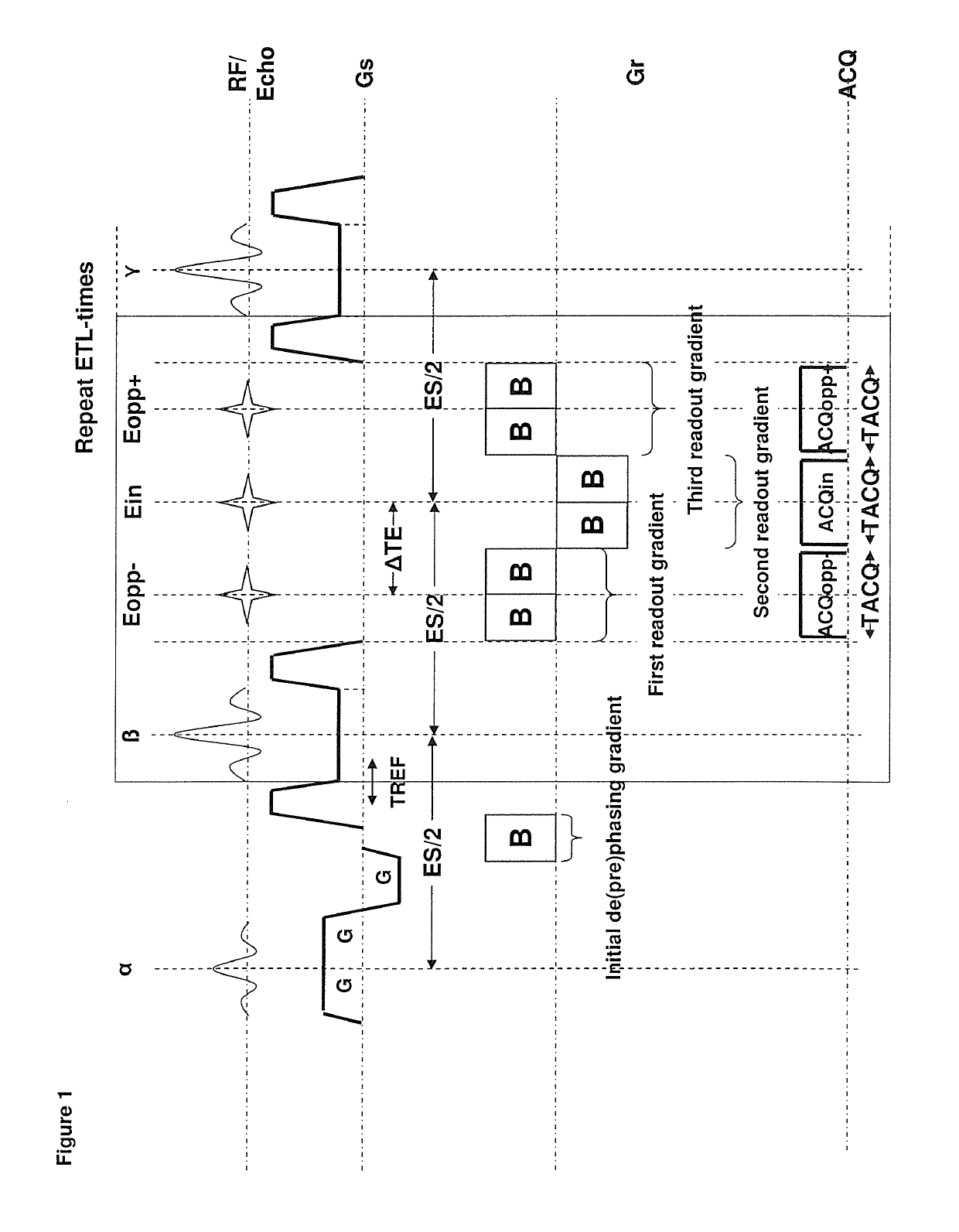
The present invention provides magnetic resonance imaging methods that use a TSE Dixon sequence with increased resolution in readout direction and a CPMG TSE n-point Dixon sequence with shortened echo spacing between refocusing pulses. These methods improve image sharpness and reduce T2 decay along the echo train. Additionally, the method achieves a particular desired phase shift between signal emerging from fat and water protons by acquiring the first and last echo asymmetrically. The readout prephasing gradient is adapted to maintain the CPMG condition. Overall, these methods enhance the accuracy and efficiency of magnetic resonance imaging.

Problems solved by technology

The disadvantage of selective lipid suppression or inversion is that these techniques rely on a homogeneous B0 field which often cannot be established in the entire imaging volume despite of shimming.
The maximum gradient strength and the maximum usable slew rate of the gradient system are limited and therefore also the resolution in readout direction.
This makes these TSE based Dixon techniques prone to motion that occur between excitations.
Further, B0 fluctuations (as a result of physiological motion or heating) between excitations leads to additional phase accumulation which cannot be distinguished from phase differences due to the fat-water frequency shift per se.
The increase in echo spacing and the reduced number of slices are problems of earlier TSE Dixon techniques.
Even an extraordinary strong gradient hardware cannot solve this problem for a human scanner since the switching between readout gradients of opposite sign would induce nerve stimulations.

Method used


Image

  • Method and apparatus for acquiring magnetic resonance data
  • Method and apparatus for acquiring magnetic resonance data
  • Method and apparatus for acquiring magnetic resonance data

Examples


second embodiment

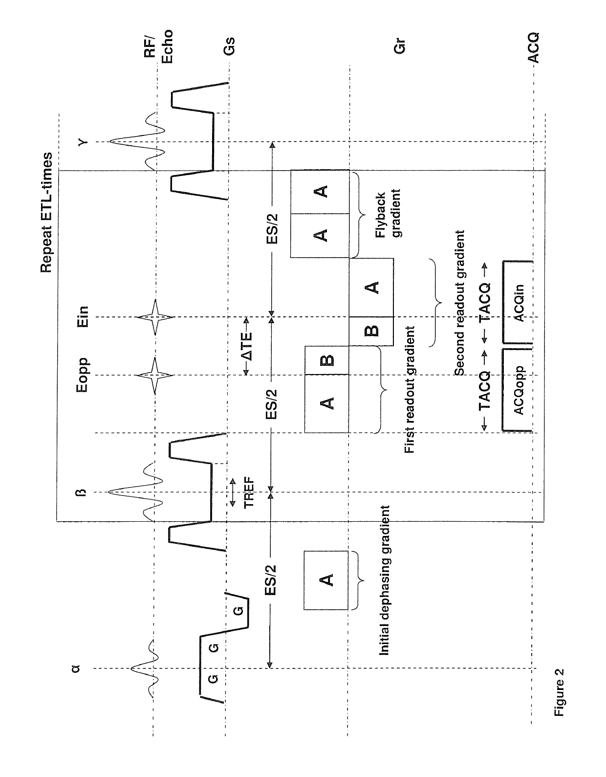
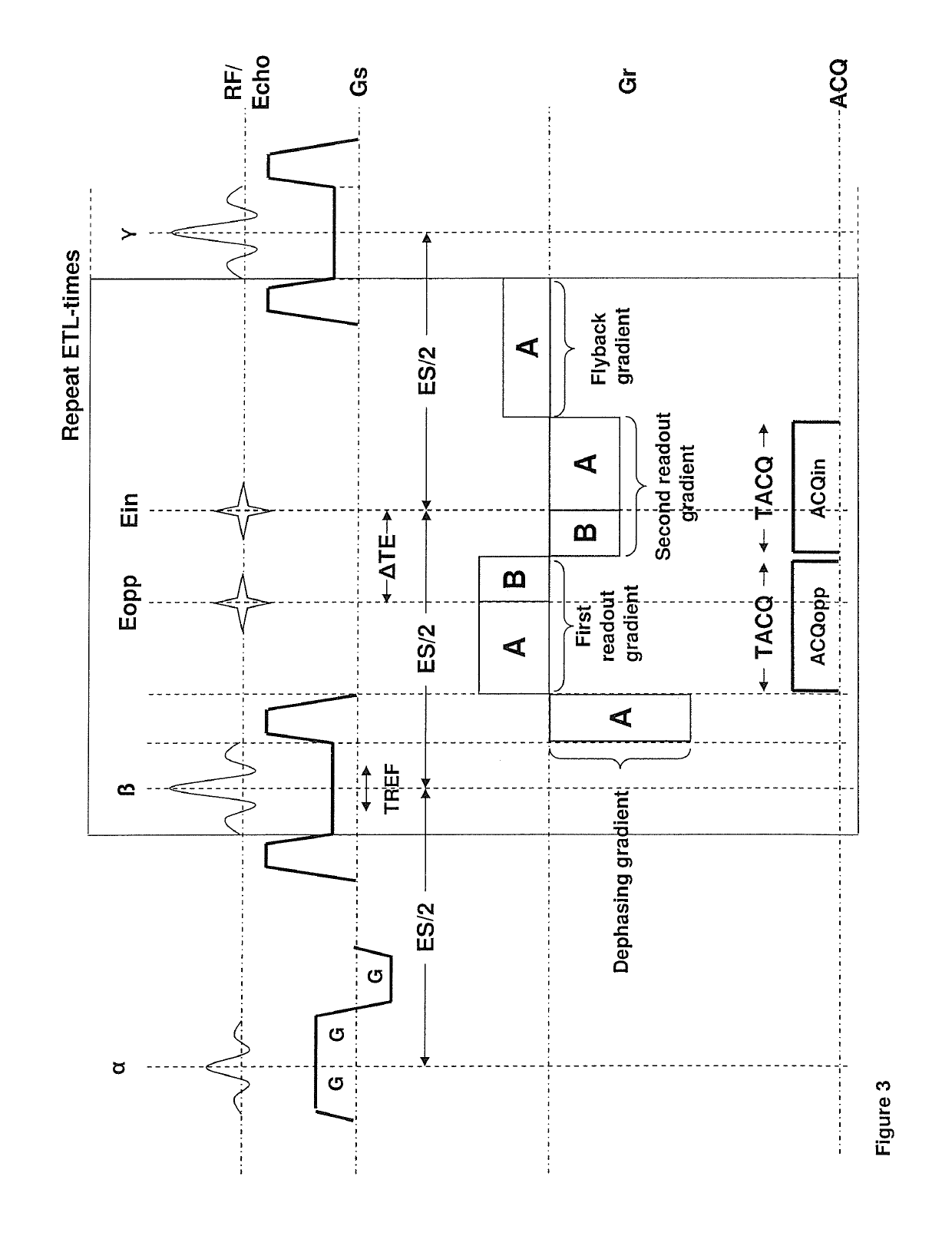
[0066]FIG. 3 shows the modified sequence. This sequence is also intended for a two point Dixon technique and also allows an increased readout moment and hence an increased resolution for a given temporal spacing between the two echoes compared to the sequence of FIG. 1. The difference to the Sequence of FIG. 2 is the absence of the prephasing gradient between excitation pulse and the first refocusing gradient. Instead the prephasing is repeated for every readout interval. It is preferably performed simultaneously with the FID Crusher and phase encoding gradient (not drawn) immediately after the refocusing pulse. The rephasing (or flyback gradient) is also modified. It has now the same absolute moment as the prephasing gradient and opposite sign so that the net moment of all gradient performed along the readout direction between two successive refocusing pulses is zero.

third embodiment

[0067]FIG. 5 illustrates a schematic diagram in the present invention having asymmetric readout. FIG. 2 and FIG. 3 are special versions of the most general design shown in FIG. 5. In the most general embodiment part of the readout prephasing is done once between the excitation pulse and the first refocusing pulse (similar to FIG. 2) and the remaining readout prephasing is repeated for every readout interval (similar to FIG. 3). The sign of the initial prephasing gradient is again equal to the sign of the first readout gradient and the sign of the repeated dephasing gradient is opposite to the sign of the first readout gradient. The moment of the flyback gradient is chosen such that the net effect on the phase of the combined action of a particular refocusing pulse and the following four gradients in readout direction (repeated dephasing gradient, two readout gradients plus flyback gradient) is zero. Hence if the moment of the repeated dephasing gradient is −C, the moment of the fly...

fourth embodiment

[0069]FIG. 6 illustrates a schematic diagram in the present invention having asymmetric readout. When both readout gradients have the same sign, the readout gradient waveform is called “monopolar” in this case. The reason for the monopolar design is that the fat-water shift is then in the same direction for both in-phase and opposed-phase image. FIG. 6 shows the sequence diagram with monopolar design. An extra gradient is needed between both gradients that operate as prephasing gradients of the second readout gradient, and it is therefore called second prephasing gradient in FIG. 6. Its moment is chosen such that it exactly compensates the moment acquired by the first readout gradient after the first echo and by the second readout gradient before the second echo. In FIG. 6 again the most general design is shown where the prephasing gradient for the first readout gradient is split into two parts. The first part is executed once between excitation pulse and first refocusing pulse and...


PUM


Abstract

In a method and apparatus for acquiring magnetic resonance (MR) data from a subject, excitation pulses and at least two refocusing pulses are applied to the subject in an MR scanner, and the MR scanner is operated to activate gradients in a readout direction that cause at least two gradient echoes to be formed between the at least two successive refocusing pulses, with a temporal distance between the at least two gradient echoes that produces a predetermined phase shift between a signal acquired from a first nuclei in the subject and a signal acquired from a second nuclei in the subject at times of the respective gradient echoes, and that include readout gradients associated respectively with a first and a last gradient echo, among said at least two gradient echoes, the readout gradients being asymmetrical.

Description

BACKGROUND OF THE INVENTION[0001]Field of the Invention[0002]The present invention relates to a method for acquiring magnetic resonance data and an apparatus for implementing such a method.[0003]Description of the Prior Art[0004]Turbo Spin Echo (TSE) is a most important sequence for T2 weighted imaging in clinical application. The primary advantage compared to conventional spin echo technique is the reduced scan time. A TSE echo train consists of an excitation pulse followed by a train of refocusing pulses. The echo formed after each refocusing pulse is individually encoded so that multiple k-space lines can be sampled after the excitation pulse. TSE is one of many acronyms used for the technique. The most important others are fast spin echo (FSE), rapid acquisition with relaxation enhancement (RARE) and fast acquisition interleaved spin echo (FAISE).[0005]Fat (lipid) signal appears bright in T2 weighted TSE imaging. The bright fat signal can obscure detection of lesions. A number o...

Claims


Application Information

Patent Timeline
Patent Type & Authority Patents(United States)
IPC IPC(8): G01R33/48G01R33/565G01R33/561G01R33/56
CPCG01R33/4828G01R33/56509G01R33/5617G01R33/5607
Inventor STEMMER, ALTOZHAO, CONG
Owner SIEMENS HEALTHCARE GMBH
Learn More