Floating roof monitoring with laser distance measurement

a technology of laser distance measurement and floating roof, which is applied in the direction of liquid/fluent solid measurement, instruments, machines/engines, etc., can solve the problems of severe accidents due to overfilling of huge storage tanks, hazardous environment on top of floating roofs, etc., and achieve the effect of improving safety and lowering costs

Active Publication Date: 2019-08-20
HONEYWELL INT INC
View PDF24 Cites 1 Cited by
  • Summary
  • Abstract
  • Description
  • Claims
  • Application Information

AI Technical Summary

Benefits of technology

[0016]Note that for a simple installation, the laser devices can also be equipped with electronic spirit levels (e.g., such as found in tablet computing devices and / or smartphones) measuring the tilt and electronically correcting the vertical level measurement. In this way it becomes less critical that the laser sensor is installed exactly plumb.
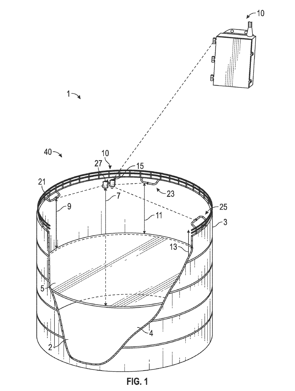
[0017]Each of the laser sensors can be installed at an approximately 120 degree (e.g., with 3 sensors or, 180 with two sensors, etc.) angle on top of the liquid tank to measure the distance between the sensors) and the floating roof. Resulting measurement data can be transmitted to a central device or computing system that calculates the exact position and depending on the application generates an alarm or forces a process associated with the floating roof and / or storage tank stop. The communication can also be routed via the radar gauge—this allows to reduce cabling and infrastructure.
[0019]Unique to the disclosed embodiments is the use of a group of laser distance measurement devices (e.g., three laser sensors) that measure distance and compare this information with liquid level measurement data. All such measurements are independent, allow for the exact detecting of the position of a floating roof, and will improve safety at lower costs than available at the moment with better performance and reliability and installation cost.

Problems solved by technology

In case of fuel and oil tanks, the environment on top of the floating roof is a hazardous or potentially hazardous environment.
Over the last several decades, severe accidents have occurred due to overfill of huge storage (e.g., oil, petroleum products, etc.) tanks (e.g., Buncefield accident in 2005 in the United Kingdom, and in Puerto Rico and Rajastan in 2009).
Such accidents sometimes cause injuries, fatalities, and result in high costs to the company owning or managing the facilities where the storage tanks are located.
Also, the company image is negatively affected.
The impact on the environment can be enormous.
One of the reasons for such accidents is often due to the lack of an adequate overfill protection that is capable of detecting a high tank fill.
Current protection systems are based on mechanical devices and are subject to failures and nuisance trips.
Monitoring a floating roof has different requirements and poses different challenges.
First, such roofs can become stuck, which might cause damage to the roof / tank, or in a worst case cause the roof to collapse and sink.
Second, the roof may make it difficult to sense high alarm conditions and increase the risk of overfill.
Either case is very costly to remediate and may also impose fines.
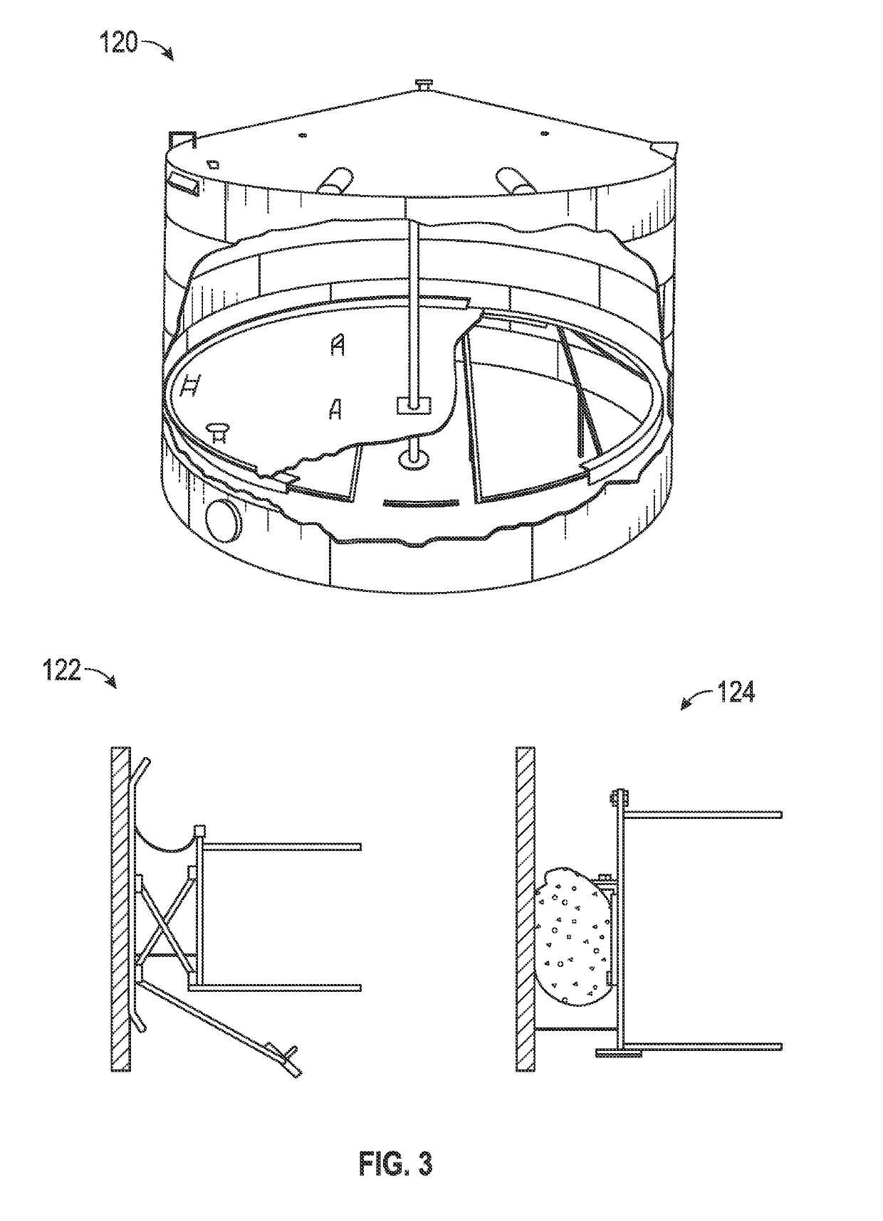
Also, the earlier discussed (rim) seal causes friction, which affects the immersion of the floating roof.
A current solution uses radar gauges, which are disadvantageous because their measurements are unreliable as there are typically obstructions on the floating roof (e.g., which cause unwanted reflections).
A highly accurate determination is difficult to obtain when measuring close to the tank wall, and measuring further away increases the installation complexity and costs.

Method used


Image

  • Floating roof monitoring with laser distance measurement
  • Floating roof monitoring with laser distance measurement
  • Floating roof monitoring with laser distance measurement

Examples


Embodiment Construction

[0032]The particular values and configurations discussed in these non-limiting examples can be varied and are cited merely to illustrate at least one embodiment and are not intended to limit the scope thereof.

[0033]The embodiments will now be described more fully hereinafter with reference to the accompanying drawings, in which illustrative embodiments of the invention are shown. The embodiments disclosed herein can be embodied in many different forms and should not be construed as limited to the embodiments set forth herein; rather, these embodiments are provided so that this disclosure will be thorough and complete, and will fully convey the scope of the invention to those skilled in the art. Like numbers refer to like elements throughout. As used herein, the term “and / or” includes any and all combinations of one or more of the associated listed items.

[0034]FIG. 1 illustrates a schematic diagram of a floating roof monitoring system 40, which incorporates laser distance measurement...


PUM


Abstract

A floating roof monitoring system and method. One or more sensors can be disposed atop a liquid storage tank having a floating roof covering liquid stored in the liquid storage tank. Each laser sensor measures the distance between the sensor and the floating roof. One or more liquid level gauges can be deployed, which measure a liquid position of the liquid stored in the liquid storage tank. A computing system communicates electronically with the laser sensor(s) and the liquid level gauge(s) to calculate the difference between the liquid position and the distance between the sensor(s) and the floating roof to determine the exact position of the floating roof and activate an alarm or force a process associated with the liquid storage tank to halt.

Description

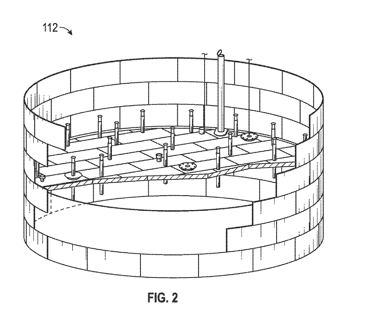
TECHNICAL FIELD[0001]Embodiments are related to floating roof tanks. Embodiments further relate to systems and methods for monitoring the floating roof of a floating roof tank.BACKGROUND OF THE INVENTION[0002]In large (e.g., bulk storage) liquid tanks, and in particular tanks used to store hydrocarbons and other chemicals, at refineries, tank terminals, and the like, which are capable of holding large amounts of ‘oil’ products, use is frequently made of a floating roof, which floats on the liquid in the tank and is displaceable in a vertical direction. Such a floating roof is capable of following the level of a liquid (e.g., hydrocarbons) when the liquid is discharged from or filled into the tank. Floating roofs of this type are used for reducing evaporative losses (from a financial perspective) and also for preventing environmental contamination (e.g., in the USA-EPA regulations (so called Title V)). Such roofs are also employed to reduce explosion risks, and for other reasons, suc...

Claims


Application Information

Patent Timeline
Patent Type & Authority Patents(United States)
IPC IPC(8): B65D90/48G01F23/292G01F23/284B65D88/34B65D90/22
CPCB65D90/48B65D88/34G01F23/292G01F23/284B65D2590/0083B65D90/22
Inventor JOOSTEN, JOHNVAN SCHIE, ARDVAN BEKKUM, FRANK
Owner HONEYWELL INT INC
Why Eureka
Try Eureka