
Seal structure for internal combustion engine

a technology for internal combustion engines and seals, which is applied in the direction of engine seals, cylinders, sealing arrangements, etc., can solve the problems of gasket receiving, compression deformation in the elongated direction, and inability to avoid the increase of cost, so as to achieve the effect of improving the sealing performance, avoiding the increase of the sealing surface pressure of the casing side seal member, and avoiding the increase of the cos

Active Publication Date: 2019-08-27
MAHLE JAPAN LTD
View PDF8 Cites 3 Cited by
  • Summary
  • Abstract
  • Description
  • Claims
  • Application Information

AI Technical Summary

Benefits of technology

The present invention is about improving the sealing performance of a chain casing seal member in an engine. This is achieved by using a flexible material, such as rubber, which is cost-effective. Additionally, a seal bead is formed on the casing seal member to further increase the seal surface pressure. The connection block section of the casing seal member acts as a reservoir section of the liquid gasket, ensuring a continuous supply of the gasket. The use of a combination of liquid gasket and seal beads enhances the sealing performance of the connection section. Moreover, the continuous pressure contact between both seal members ensures a favorable seal line continuity.

Problems solved by technology

However, since the gasket intervened between the engine main body section and the chain casing provides a hybrid structure, for example, of a rubber material and a metallic material, an increase of cost cannot be avoided.
In addition, since, in the structure described in Patent Document 2, the gasket intervened between the engine main body section and the chain casing is formed of a single material such as rubber or so forth, the seal structure described in Patent Document 2 is advantageous in terms of cost but, since a receiving surface of the gasket is not provided against a fastening force of the head cover or the oil pan, both of which being the cover members, the gasket receives only a compression deformation in the elongate direction and an accompanied reaction force becomes insufficient.
Thus, although the increase in the seal surface pressure is achieved, naturally there is a limit.

Method used


Image

  • Seal structure for internal combustion engine
  • Seal structure for internal combustion engine
  • Seal structure for internal combustion engine

Examples


first embodiment

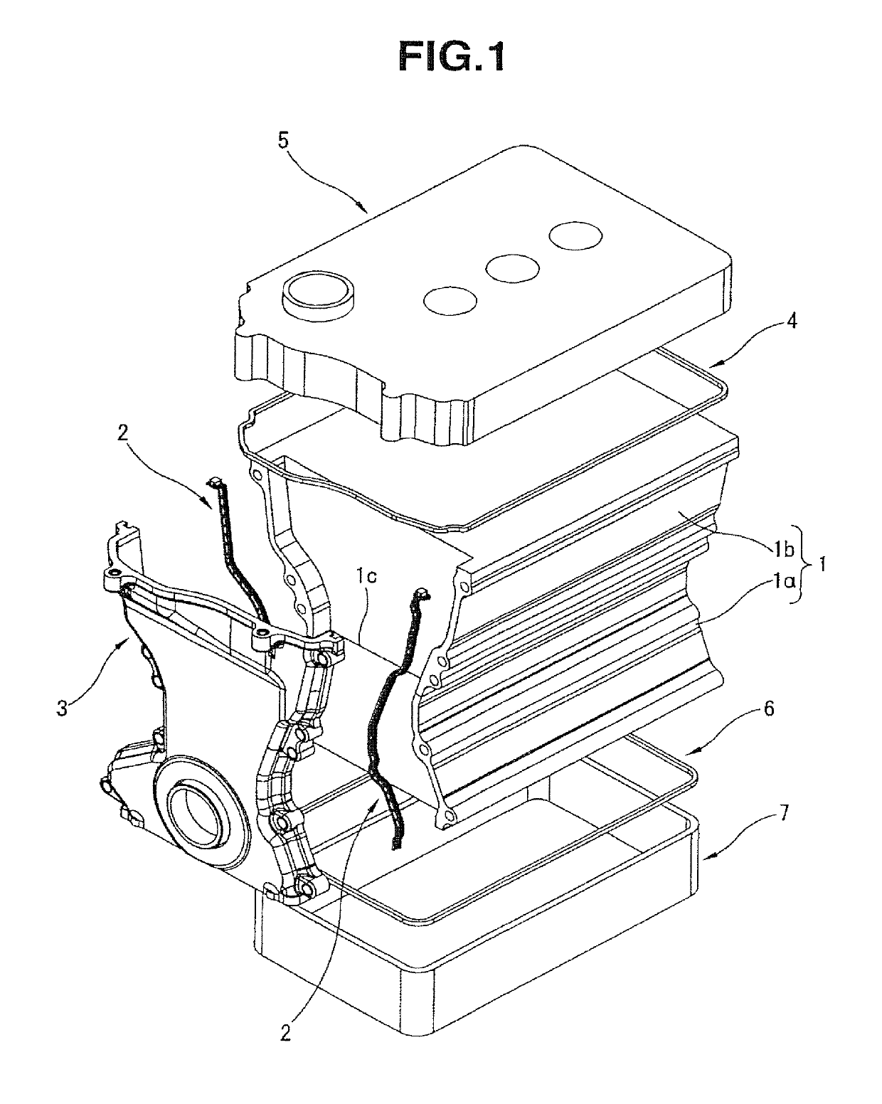
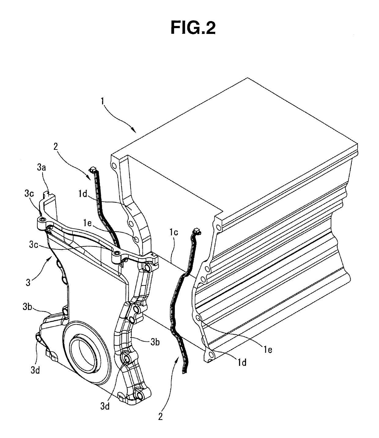
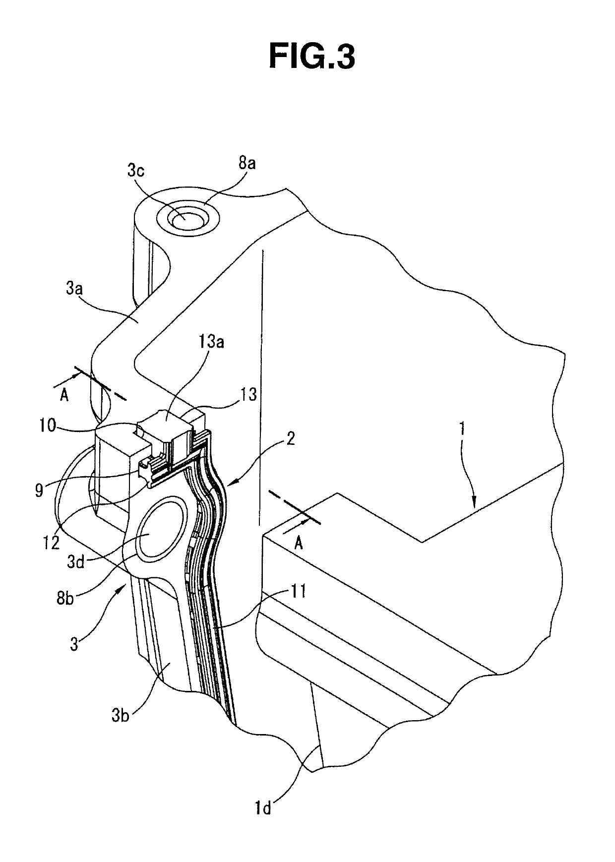
[0066]Hence, extremely thick connection block section 13 of each casing side gasket2 is received by bottom surface 10a of receiving concavity 10 which functions as a receiving surface of receiving concavity 10 at chain casing 3 side shown in FIG. 5 and, while connection block section 13 projected toward head cover 5 side is compression deformed, seal beads 4a, 4b of cover side gasket 4 are brought in contact with the two wisps of seal beads 4a, 4b of cover side gasket 4 under pressure so that both gaskets 2, 5 are mutually connected together.

[0067]Therefore, even if, for example, in a state in which chain casing 3 is assembled to engine main body section 1, a minute step difference between the junction surface of engine main body section 1 side to head cover 5 and the junction surface of chain casing 3 side to the head cover 5 is developed, cover side gasket 4 and connection block section 13 of each casing side gasket 2 and casing side gasket 2 can faithfully follow the step differ...

second embodiment

[0071]In a second embodiment shown in FIG. 8, FIG. 8 is common to FIG. 6 in that the two wisps of seal beads 16a, 16b are formed on the seal surface of connection block section 13 against engine main body section1.

[0072]In addition, the seal surface of connection block section 13 one step digs down between the two wisps of seal beads 16a, 16b so that a groove section 17a which is exposed to flat abutting surface 13a is formed. In a case where a back surface side of connection block section 13 opposite to the seal surface of connection block section 13, another groove section 17b is similarly formed to be exposed to flat abutting surface 13a.

[0073]In a case where only two wisps of seal beads 16a, 16b are formed on connection block section 13, it is necessary to more or less crush these seal beads 16a, 16b in order to exhibit a natural seal function. Hence, as described before, when the space between both seal beads 16a, 16b functions as the reservoir section of the liquid gasket, th...

fourth embodiment

[0078]In the fourth embodiment, projection section 19 is provided so that the space between these two wisps of seal bead fragments 18a, 18b which functions as the reservoir section of the liquid gasket can more assuredly be secured.


PUM


Abstract

A seal structure for an internal combustion engine comprising: a cover side seal member which extends on upper surface sides or lower surface sides of both of an engine main body section and a chain casing and pressed and held against a cover member; a casing side seal member arranged at left or right end section of one end surfaces of the engine main body section onto which the chain casing is attached and pressed and held against the chain casing; a receiving concavity formed to extend on a junction surface of the chain casing to the cover member; and an extremely thick connection block section formed integrally on one end section of the casing side seal member, fitted into and retained by the receiving concavity, and projected more toward the cover member side than a junction surface of the chain casing to the cover member in a free state.

Description

FIELD OF THE INVENTION[0001]The present invention relates to a seal structure for an internal combustion engine including an engine main body section, a chain casing, and a cover member such as a head cover, an oil pan, or so forth:[0002]More particularly, the present invention relates to the seal structure in a junction of three members of the engine main body section, the chain casing, and the cover member.BACKGROUND OF THE INVENTION[0003]For example, each of Patent Documents 1 and 2 proposes such a kind of the seal structure for the internal combustion engine.[0004]In the seal structure described in Patent Document 1, attention has been paid to a specificity of the seal structure extending on three elements of the engine main body section, the chain casing, and the cover member and a gasket intervened between the engine main body section and the chain casing is formed integrally with a metallic spacer grasped between the engine main body section and the chain casing, at both end ...

Claims


Application Information

Patent Timeline
Patent Type & Authority Patents(United States)
IPC IPC(8): F02F11/00F02F7/00F16J15/06F16J15/10F16J15/14F02F1/24
CPCF02F11/00F02F11/002F02F7/006F02F2007/0078F16J15/062F02F1/24F02F7/0043F16J15/104F16J15/14
Inventor ITO, DAIZONONAKA, ATSUSHITANI, SEIJI
Owner MAHLE JAPAN LTD
Learn More