Apparatus for refining molten aluminum alloys

a technology of aluminum alloy and apparatus, which is applied in the direction of lighting and heating apparatus, charge manipulation, furniture, etc., can solve the problems of eliminating chlorine gas, unsatisfactory effects in casting process and finished product properties, etc., and achieves the effect of reducing the size of gas bubbles and reducing the amount of turbulen

Active Publication Date: 2019-08-27
PYROTECK INC
View PDF11 Cites 0 Cited by
  • Summary
  • Abstract
  • Description
  • Claims
  • Application Information

AI Technical Summary

Benefits of technology

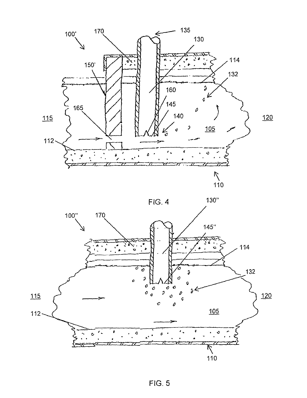
[0007]In one embodiment, the dispensing rim of the elongated dispensing rod includes at least one notch positioned inwardly along the dispensing rim. This configuration allows for a lower gas flow or gas pressure through the dispensing rim thereby reducing the size of gas bubbles distributed from the dispensing rim thereby reducing an amount of turbulence along a surface of the molten material. This configuration assists with mixing the flux with the molten material.
[0009]In another embodiment, a method of mixing flux within a flow of molten material is provided. An elongated dispensing rod having a hollow interior and a dispensing rim is provided within the flow of molten material. The dispensing rim of the dispensing rod is positioned adjacent to and downstream from a baffle plate within the flow of molten material. A flux is introduced to the dispensing rod to exit through the dispensing rim as the flow of molten material is manipulated as it flows passed the baffle plate. The flux is distributed into the flow of molten material having been manipulated by the baffle plate to increase the distribution area of the flux thereby improving flux mixing as it mixes within the flow of molten material.

Problems solved by technology

These impurities may cause undesirable effects in the casting process and to the properties of the finished product.
However, there has been pressure to eliminate the use of chlorine gas in applications such as these because of the environmental damage and burden of handling.

Method used


Image

  • Apparatus for refining molten aluminum alloys
  • Apparatus for refining molten aluminum alloys
  • Apparatus for refining molten aluminum alloys

Examples


Embodiment Construction

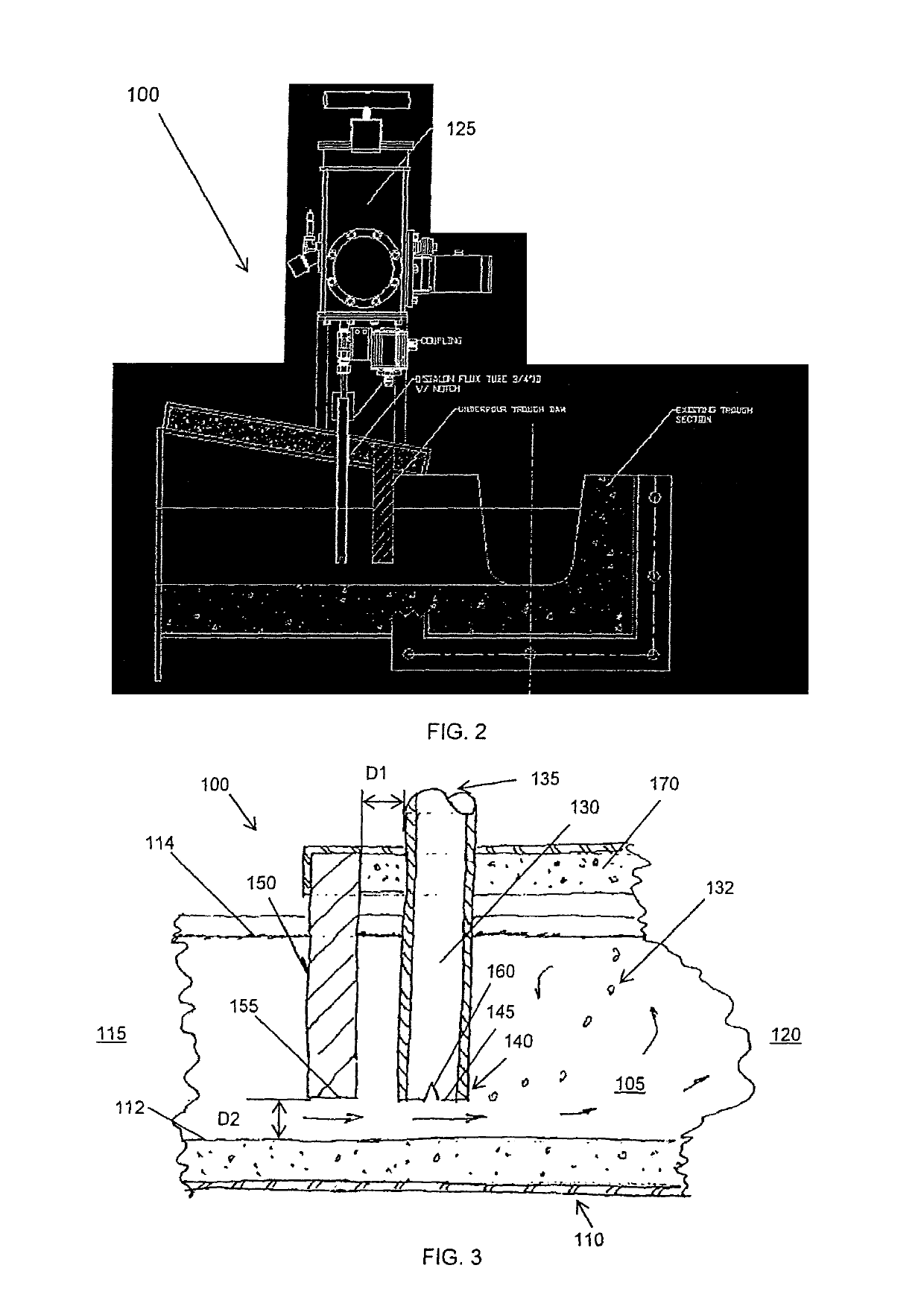
[0024]Reference will now be made in detail to the embodiments of the disclosure, examples of which are illustrated in the accompanying drawings. Whenever possible, like reference numbers will be used to refer to like components or parts. For purposes of this description, similar aspects among the various embodiments described herein will be referred to by similar reference numbers. Similar features may be described utilizing a reference number having an apostrophe (′) or double apostrophe (″) for clarity and this description is not limited as to the combination of features as described. As will be appreciated, however, the structure of the various aspects can be different among the various embodiments.

[0025]For purposes of this disclosure, the term “molten material” will be used to describe aluminum or a mixture of alloys that includes aluminum, other metal element or alloy that has been melted into a molten form and is not limited as to the various elements that are included therei...


PUM

PropertyMeasurementUnit
mixing fluxaaaaaaaaaa
sizeaaaaaaaaaa
areaaaaaaaaaaa

Abstract

Disclosed is a flux injector assembly and method for refining a molten material, wherein at least a portion of the material is aluminum, as it flows through a trough. A dispensing rod having a hollow body and a dispensing rim is configured to allow a flux and / or inert gas to travel through the hollow body and be injected into the molten material through the dispensing rim as the molten material flows through the trough. A baffle plate is configured to be positioned within the molten material in the associated trough to allow the molten material to flow passed the baffle plate. The elongated dispensing rod is positioned at a downstream location relative to the baffle plate. The rate of flow of molten material is increased as it passes the dispensing rim of the elongated dispensing rod to inject and mix the flux within the molten aluminum alloy.

Description

[0001]This application claims the benefit of U.S. Provisional Application No. 62 / 032,853, filed Aug. 4, 2014, the disclosure of which is herein incorporated by reference.BACKGROUND[0002]The present disclosure relates to an apparatus and method for refining molten aluminum alloys. It finds particular application in conjunction with a flux injection assembly configured to introduce flux to the molten aluminum alloy as it flows through a trough, and will be described with particular reference thereto. However, it is to be appreciated that the present exemplary embodiment is also amenable to other like applications.[0003]Molten metals such as aluminum and aluminum alloys include trace amounts of impurities that are desired to be removed during refinement. In known refinement processes, aluminum is melted within a furnace and then transferred to a casting machine for metal formation. The aluminum is typically transferred from the furnace to the casting machine through a trough. The molte...

Claims


Application Information

Patent Timeline
Patent Type & Authority Patents(United States)
IPC IPC(8): C22B21/00F27D3/16C22B21/06F27D27/00
CPCF27D3/16C22B21/062C22B21/064F27D27/00F27D2003/166F27D2003/168F27D2003/169Y02P10/20C22B9/00
Inventor WILLIAMS, TABBKLEPACKI, MICHAELMORAN, RYAN
Owner PYROTECK INC
Why Eureka
Try Eureka