
Method for determining a pulse duration T90 of a 90° pulse in a nuclear magnetic measuring method and respective nuclear magnetic flowmeter

a nuclear magnetic measuring method and pulse duration technology, applied in the direction of measuring devices, instruments, magnetic resonance measurements, etc., can solve the problem of requiring a large amount of time for carrying out the measurement series, and achieve the effect of reducing the number of measurements

Active Publication Date: 2019-09-10
KRONE GMBH
View PDF5 Cites 0 Cited by
  • Summary
  • Abstract
  • Description
  • Claims
  • Application Information

AI Technical Summary

Benefits of technology

[0027]It has been found that the coil reactance XL of the coil impedance ZL changes only little at a plurality of applications. For this reason, in an implementation alternative to the above implementation, the coil reactance XL is assumed to be a constant and the coil resistance RL is determined using the generator resistance RS, the angular resonance frequency ω0 and either the matching capacitance CM or the tuning capacitance CT. This is possible because the equations for the circuit arrangement according to Kirchhoff's circuit laws are over-determined due to the assumption of a constant coil reactance XL. Thus, either the matching capacitance CM or the tuning capacitance CT can be used for determining the coil resistance RL. This implementation offers the advantage of a reduced effort in determining the coil resistance RL.

Problems solved by technology

The prior art has, in particular, the disadvantage of requiring a large amount of time for carrying out the measuring series.

Method used


Image

  • Method for determining a pulse duration <i>T</i><sub>90 </sub>of a 90° pulse in a nuclear magnetic measuring method and respective nuclear magnetic flowmeter

Examples


Embodiment Construction

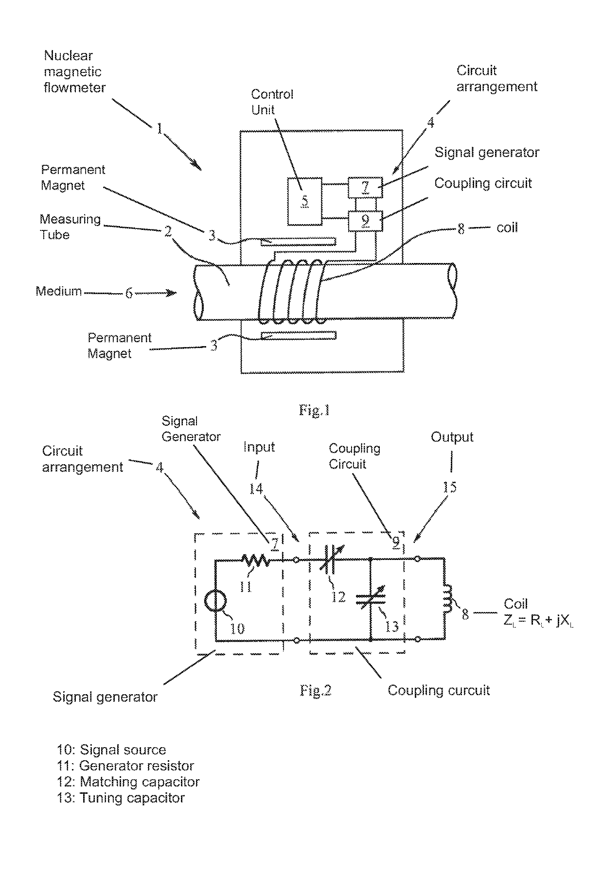
[0043]FIG. 1 shows an embodiment of a nuclear magnetic flowmeter 1 for nuclear magnetic measuring methods in operation. FIG. 1 shows the measuring tube 2, the permanent magnets 3, the circuit arrangement 4 and the control unit 5 of the nuclear magnetic flowmeter 1.

[0044]The measuring tube 2 has a medium 6 flowing through it, wherein the medium 6 has several phases. The permanent magnets 3 generate a magnetic field that magnetizes the medium 6 in a volume so that the medium 6 has a Larmor precession with the angular Larmor frequency ωP. The nuclear magnetic flowmeter 1 is designed to carry out nuclear magnetic measuring methods, which, for example, determine the flow velocity of the phases of the medium 6 through the measuring tube 2 and the portions of the individual phases in the medium 6.

[0045]FIG. 2 shows a simplified circuit diagram of the essential elements of the circuit arrangement 4. The circuit arrangement 4 is comprised of the signal generator 7 for generating a 90° pulse,...


PUM

PropertyMeasurementUnit
angleaaaaaaaaaa
impedanceaaaaaaaaaa
impedanceaaaaaaaaaa

Abstract

A method for determining a pulse duration T90 of a 90° pulse in a nuclear magnetic measuring method. A signal generator has a known generator resistance RS, wherein a coil has a coil impedance ZL with a coil resistance RL and a coil reactance XL, wherein a coupling circuit has an adjustable matching capacitance CM and an adjustable tuning capacitance CT, and wherein the medium has a Larmor precession having an angular Larmor frequency ωP. The time needed for determining the pulse duration T90 of the 90° pulse is reduced by the matching capacitance CM and the tuning capacitance CT being set so that the angular resonance frequency ω0 corresponds to the angular Larmor frequency ωP and by power matching being present between the signal generator and the coil. The coil resistance RL is determined and the pulse duration T90 is determined as a function of the coil resistance RL.

Description

BACKGROUND OF THE INVENTIONField of the Invention[0001]The invention relates to a method for determining a pulse duration T90 of a 90° pulse in a nuclear magnetic measuring method with a circuit arrangement. Thereby, the circuit arrangement has a signal generator for generating the 90° pulse, a coil for transmitting the 90° pulse to a medium, a coupling circuit and an angular resonance frequency ω0. The signal generator has a known generator resistance RS. The coil has a coil impedance ZL with a coil resistance RL and a coil reactance XL according to ZL=RL+jXL. The coupling circuit has a matching capacitor having an adjustable matching capacitance CM and a tuning capacitor having an adjustable tuning capacitance CT. The medium is magnetized by a magnetic field for the nuclear magnetic measuring method and has a Larmor precession having an angular Larmor frequency ωP.Description of Related Art[0002]The invention further relates to a nuclear magnetic flowmeter for a nuclear magnetic m...

Claims


Application Information

Patent Timeline
Patent Type & Authority Patents(United States)
IPC IPC(8): G01R33/563G01R33/44G01N24/08G01R33/30G01F1/716G01R33/36
CPCG01R33/56308G01R33/36G01R33/3628G01R33/44G01F1/716G01N24/08G01R33/307G01R33/3607
Inventor TROMP, RUTGER REINOUT
Owner KRONE GMBH
Learn More