Supercharge Your Innovation With Domain-Expert AI Agents!

Antenna tuning system and method thereof

a tuning system and antenna technology, applied in the direction of antennas, simultaneous aerial operations, transmission monitoring, etc., can solve the problems of multi-path fading and interference caused by omni-antenna, and achieve the effect of avoiding energy was

Active Publication Date: 2019-09-10
ACCTON TECHNOLOGY CORPORATION
View PDF11 Cites 1 Cited by
  • Summary
  • Abstract
  • Description
  • Claims
  • Application Information

AI Technical Summary

Benefits of technology

The present invention is an antenna system that uses different design circuits to tune the antenna for better performance. This system can generate different antenna radiation patterns to concentrate energy in the direction of a target station and avoid wasting energy on unauthorized or rogue stations. The technical effect of this invention is improved efficiency and accuracy in wireless communication.

Problems solved by technology

In the existing technology, when a general directional antenna is configured, the direction of the general directional antenna is fixed; accordingly, the fading caused by multi-path will be not solved.
The Omni-antenna has the advantage of covering greater angles; however, the Omni-antenna still cannot solve the interference caused by the rogue stations.

Method used


Image

  • Antenna tuning system and method thereof
  • Antenna tuning system and method thereof
  • Antenna tuning system and method thereof

Examples


first embodiment

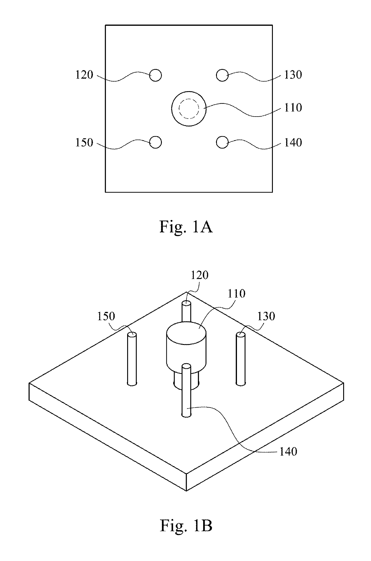
[0025]FIG. 1A and FIG. 1B are block diagrams for configurations of main antenna and a plurality of parasitic antennas of the antenna tuning system according to the present invention. In FIG. 1A and FIG. 1B, four parasitic antennas 120, 130, 140, and 150 surround the main antenna 110. The main antenna 110 and the parasitic antennas 120, 130, 140, and 150 of the present invention are monopole antennas in the present embodiment. The distance between the main antenna 110 and the parasitic antennas 120, 130, 140, and 150 is quarter of the operating wavelength in the present embodiment. However, the actual planning is not limited thereto. The antenna tuning system of the present invention can determine that the radiation energy of the target station generated by different parasitic antennas cooperating with the main antenna 110. The antenna tuning system also chooses the related parasitic antenna having the greatest resonance effect so as to let the target station have the greatest commun...

second embodiment

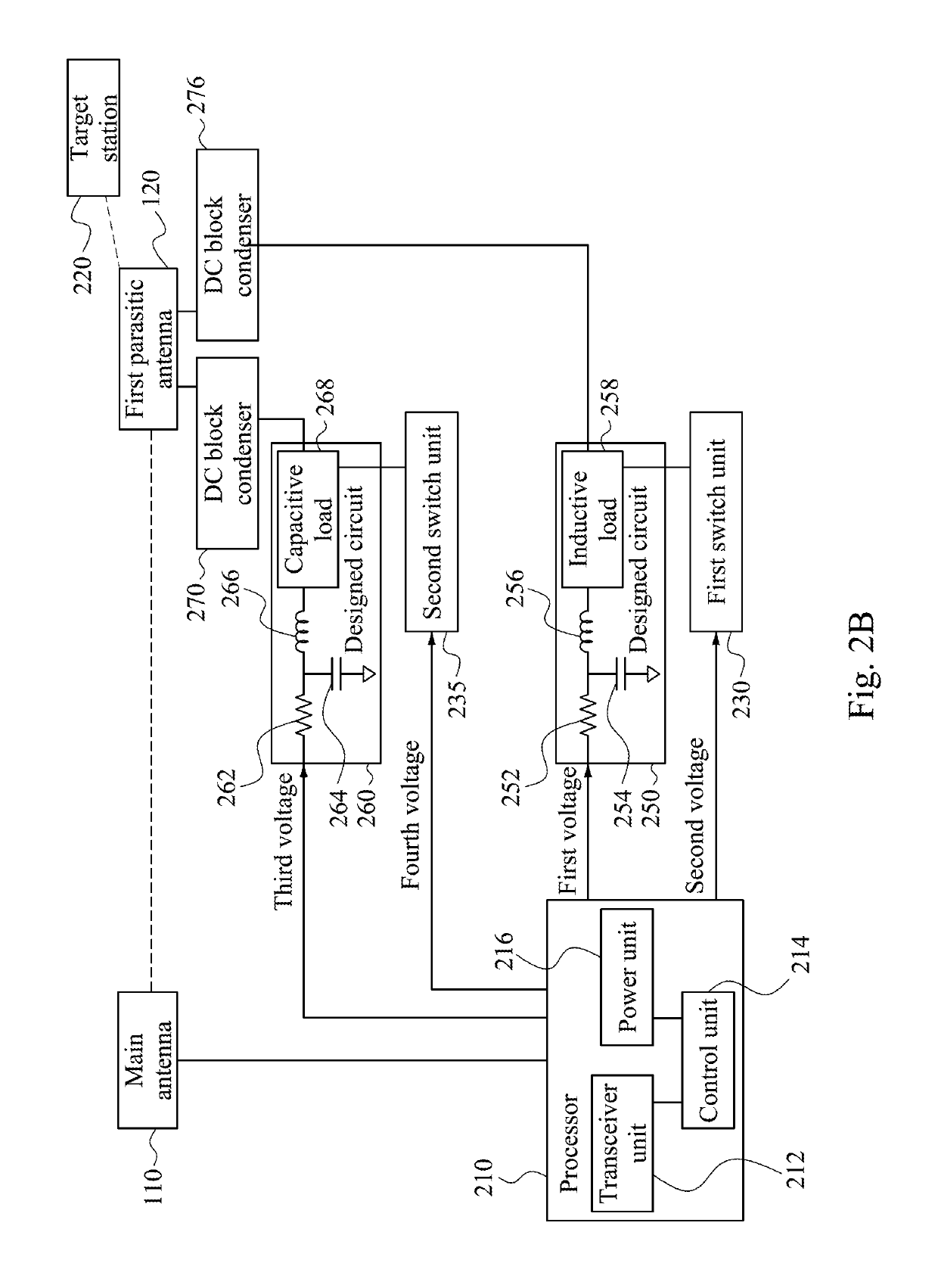
[0034]In the second embodiment, the control unit 214 can choose the first switch unit 230 or the second switch unit 235 of the two switch units and turns on it. Accordingly, the antenna tuning system of the present invention can have the inductive load 258 and the capacitive load 268 selectively. It is worth noting that capacitive components, for example, DC block condensers 270 and 276, are installed at the connected point between the first parasitic antenna 120, the inductive load 258, and the capacitive load 268 to separates different DC control signal from the first switch unit 230 and the second switch unit 235 respectively in order to prevent the two switch units from interfering each other. Therefore, the processor 210 controls the first switch unit 230 through the first voltage and the second voltage and controls the second switch unit 235 through the third voltage and the fourth voltage in order to implement choosing or switching different property of reactive loads. For ex...


PUM


Abstract

The present invention discloses an antenna tuning system and method thereof. The method comprises the following steps: choosing a parasitic antenna that combined with a main antenna, the strongest received signal strength indicator of a target station is detected; controlling the selected parasitic antenna that combined with a main antenna, to generate a scattering resonance through turning on or off a switch unit; and controlling a diffraction radiation pattern between the main antenna and the selected parasitic antenna through adjusting a load of a designed circuit.

Description

RELATED APPLICATIONS[0001]This application claims priority to Taiwan Application Serial Number 105142535, filed Dec. 21, 2016, which is herein incorporated by reference.BACKGROUNDField of Invention[0002]The present invention relates to an antenna tuning system and method thereof.Description of Related Art[0003]In the existing technology, when a general directional antenna is configured, the direction of the general directional antenna is fixed; accordingly, the fading caused by multi-path will be not solved. The antenna supporting MIMO system is developed, and the Omni-antenna is chosen. The Omni-antenna has the advantage of covering greater angles; however, the Omni-antenna still cannot solve the interference caused by the rogue stations.SUMMARY[0004]The present invention provides an antenna tuning system. The antenna tuning system uses various design circuits containing reactive loads to form different antenna resonance effect so as to generate different antenna radiation pattern....

Claims


Application Information

Patent Timeline
Patent Type & Authority Patents(United States)
IPC IPC(8): H04M3/16H01Q5/385H01Q3/24H01Q19/32H04B17/318
CPCH01Q5/385H01Q19/32H01Q3/247H04B17/318H01Q3/26
Inventor LIU, I-RULO, WEN-PINKANG, HSIN-HSIUNGFU, YANG-TELIU, CHANG-CHENGLIAO, YEN-LINCHEN, YI-CHANGCHOU, LI-HUA
Owner ACCTON TECHNOLOGY CORPORATION
Features
  • R&D
  • Intellectual Property
  • Life Sciences
  • Materials
  • Tech Scout
  • Unparalleled Data Quality
  • Higher Quality Content
  • 60% Fewer Hallucinations
Learn More