Stator for rotary electric machine having respective terminal wires connected to a connecting member

a technology of connecting member and terminal wire, which is applied in the direction of stator/rotor body manufacturing, magnetic circuit shape/form/construction, magnetic circuit rotating parts, etc., can solve the problems of reducing productivity, increasing the axial dimension of the stator, and reducing productivity, so as to achieve the effect of increasing productivity

Inactive Publication Date: 2019-09-10
MITSUBISHI ELECTRIC CORP
View PDF13 Cites 0 Cited by
  • Summary
  • Abstract
  • Description
  • Claims
  • Application Information

AI Technical Summary

Benefits of technology

[0008]The present invention aims to solve the above problems and an object of the present invention is to provide a stator for a rotary electric machine that increases productivity by orienting welding directions of all connecting portions of a stator winding in a radial direction, and that also suppresses increases in axial dimensions by lowering axial height positions of all of the connecting portions of the stator winding.
[0013]Consequently, the welding directions of the connecting portions of the stator winding can all be oriented in a radial direction, increasing productivity.

Problems solved by technology

Consequently, one problem has been that it is necessary to perform welding together of the terminal wires of the winding bodies that constitute phase windings and welding of the AC connecting portions in different steps, reducing productivity.
Furthermore, if welding together the terminal wires of the winding bodies that constitute phase windings and welding of the AC connecting portions are performed using the same equipment, then complicated steps such as tilting the stator core are required for every welded position, further leading to reductions in productivity.
Thus, one problem has been that the busbar module protrudes axially outward from the winding bodies that are wound onto the stator core, increasing the axial dimensions of the stator, and leading to increases in the size of the rotary electric machine.

Method used


Image

  • Stator for rotary electric machine having respective terminal wires connected to a connecting member
  • Stator for rotary electric machine having respective terminal wires connected to a connecting member
  • Stator for rotary electric machine having respective terminal wires connected to a connecting member

Examples


embodiment 1

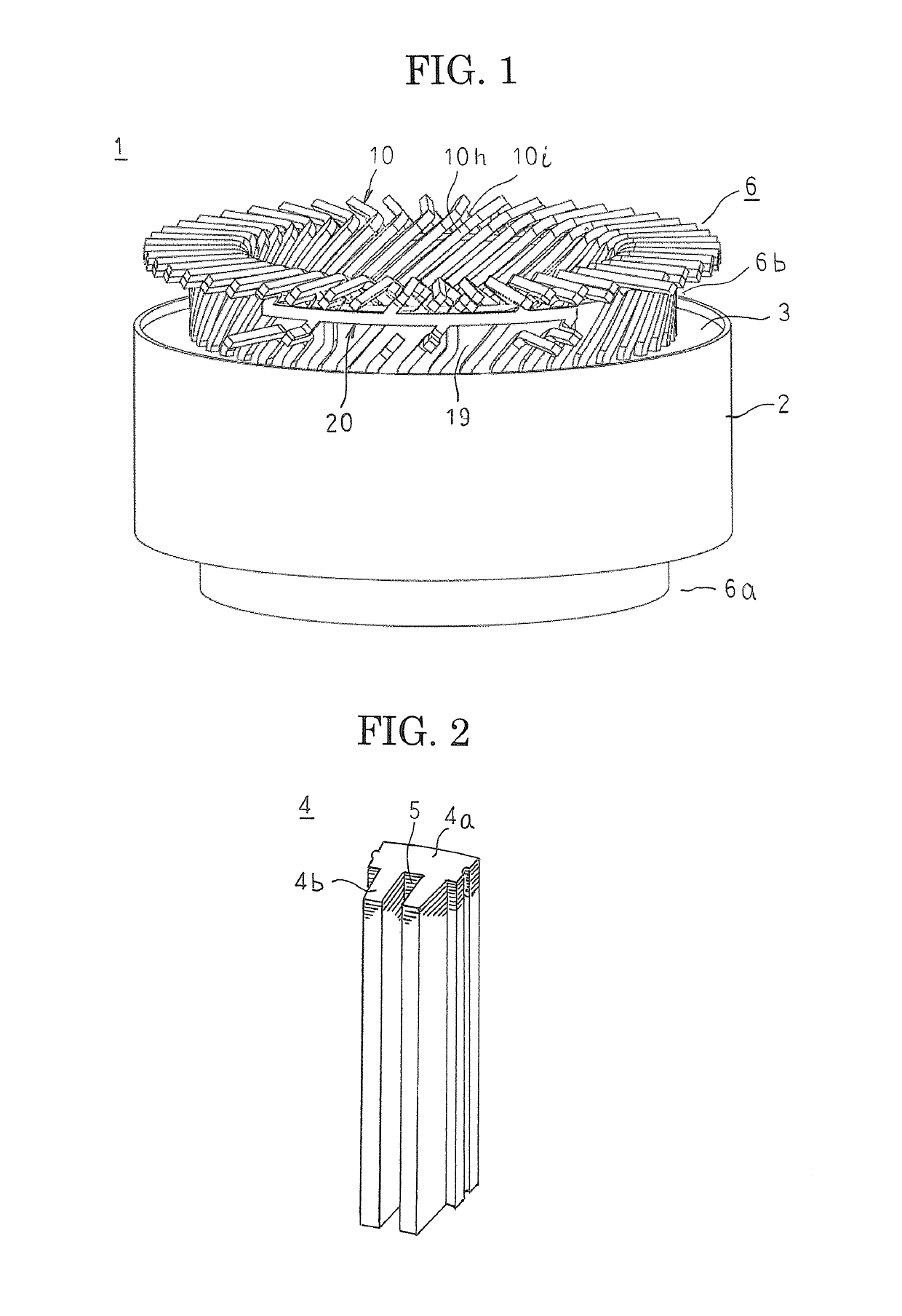
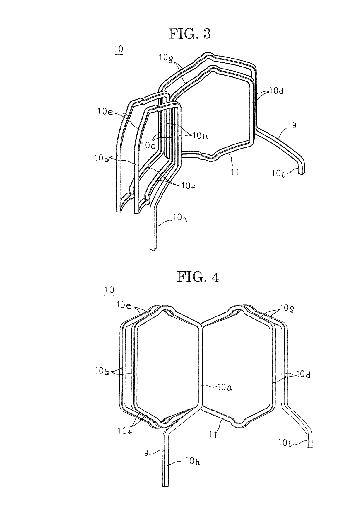
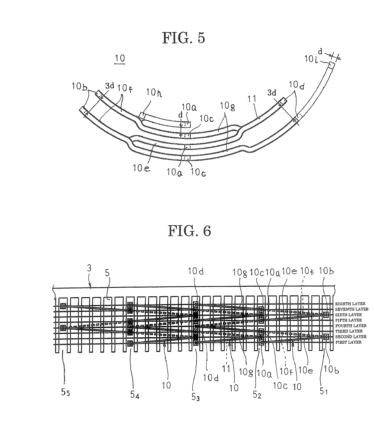
[0032]FIG. 1 is an oblique projection that shows a stator for a rotary electric machine according to Embodiment 1 of the present invention, FIG. 2 is an oblique projection that shows a core block that constitutes part of a stator core in the stator for a rotary electric machine according to Embodiment 1, FIG. 3 is an oblique projection that shows a winding body that constitutes part of a stator winding in the stator for a rotary electric machine according to Embodiment 1, FIG. 4 is a front elevation that shows the winding body that constitutes part of the stator winding in the stator for a rotary electric machine according to Embodiment 1, FIG. 5 is an end elevation viewed from a side near second coil ends that shows the winding body that constitutes part of the stator winding in the stator for a rotary electric machine according to Embodiment 1, FIG. 6 is a partial end elevation viewed from a side near second coil ends that shows a state in which three winding bodies that constitut...


PUM


Abstract

Winding bodies include: a first terminal wire that extends outward at a first axial end of a stator core from a radially innermost position inside slots; and a second terminal wire that extends outward at the first axial end of the stator core from a radially outermost position inside the slots, the first terminal wires are each led radially outward over coil ends of the stator winding, the second terminal wires are each led radially outward at positions that are nearer to the stator core than end portions of the first terminal wires that are led radially outward over the coil ends of the stator winding, and end portions of intraphase connecting second terminal wires are stacked in an axial direction with, placed in contact with, and connected to end portions of intraphase connecting first terminal wires that are subject to connection therewith.

Description

BACKGROUND OF THE INVENTION[0001]1. Field of the Invention[0002]The present invention relates to a stator for a rotary electric machine such as an electric motor or a generator, for example, and particularly relates to a connecting construction for a stator winding.[0003]2. Description of the Related Art[0004]In a conventional stator for a rotary electric machine according to Patent Literature 1, respective winding bodies that are produced by winding conductor wires onto a stator core are configured such that two terminal wires of the conductor wires protrude in identical axial directions of a stator core from a radially inner side and a radially outer side. The terminal wires of winding bodies that constitute phase windings are each bent approximately perpendicularly, and are extended radially outside the stator core. Then, the end portions of the terminal wires on the radially inner side of the winding bodies that are extended radially outside the stator core are stacked together ...

Claims


Application Information

Patent Timeline
Patent Type & Authority Patents(United States)
IPC IPC(8): H02K3/28H02K1/16H02K3/12H02K15/02H02K15/085H02K1/27H02K15/04H02K3/50
CPCH02K3/28H02K1/16H02K3/12H02K15/085H02K15/024H02K15/0435H02K1/276H02K3/50
Inventor NAKAMURA, MASASHIEGASHIRA, KOHEIHINO, TATSUROYOKOGAWA, TETSUYASAWA, SHINKICHI
Owner MITSUBISHI ELECTRIC CORP
Why Eureka
Try Eureka