Systems and methods for optimizing landing performance

a technology of landing performance and optimization methods, applied in the field of navigational aids, can solve the problems of unnecessarily high cost, depreciation of brakes, and unnecessary inflating of problems, and achieve the effects of increasing the range of associated costs, accelerating the depreciation of brakes, and reducing the cost of fuel consumption

Active Publication Date: 2019-09-17
HONEYWELL INT INC
View PDF21 Cites 2 Cited by
  • Summary
  • Abstract
  • Description
  • Claims
  • Application Information

AI Technical Summary

Benefits of technology

[0017]Regardless of the selected exit-way, pilots often employ brake settings higher than necessary. As may be appreciated, utilizing higher brake settings than necessary accelerates depreciation of the brakes and increases a variety of associated costs.
[0018]Exemplary embodiments of a novel disclosed system for optimizing landing performance (FIG. 2, 102) are provided. The disclosed system for optimizing landing performance 102 is directed to the technical problems of over-consumption of brakes and unnecessarily costly landing cycles, due to employing non-optimal equipment configurations. The system for optimizing landing performance identifies an optimized equipment configuration to achieve the optimized landing performance. As used herein, an “equipment configuration” means a given combination of a brake setting and a thrust reverser configuration, and an “optimal” equipment configuration is the lowest cost equipment configuration that will achieve the desired safe landing performance.

Problems solved by technology

With respect to brakes, in some instances, a technical problem occurs in that they degrade more quickly than expected, i.e., they do not support as many landing cycles as they are purported to support.
This problem inflates costs unnecessarily.
A potential contributor to this problem is that it has been determined that pilots often utilize auto brake settings at levels higher than required.
Therefore, technical problems to address for optimal landing performance include, first, the cost tradeoff between brake usage, thrust reverser configuration, and fuel consumption, and second, a way to provide this navigational assistance to the pilot.

Method used


Image

  • Systems and methods for optimizing landing performance
  • Systems and methods for optimizing landing performance
  • Systems and methods for optimizing landing performance

Examples


Embodiment Construction

[0015]The following detailed description is merely illustrative in nature and is not intended to limit the embodiments of the subject matter or the application and uses of such embodiments. As used herein, the word “exemplary” means “serving as an example, instance, or illustration.” Thus, any embodiment described herein as “exemplary” is not necessarily to be construed as preferred or advantageous over other embodiments. The embodiments described herein are exemplary embodiments provided to enable persons skilled in the art to make or use the invention and not to limit the scope of the invention that is defined by the claims. Furthermore, there is no intention to be bound by any expressed or implied theory presented in the preceding technical field, background, summary, or the following detailed description.

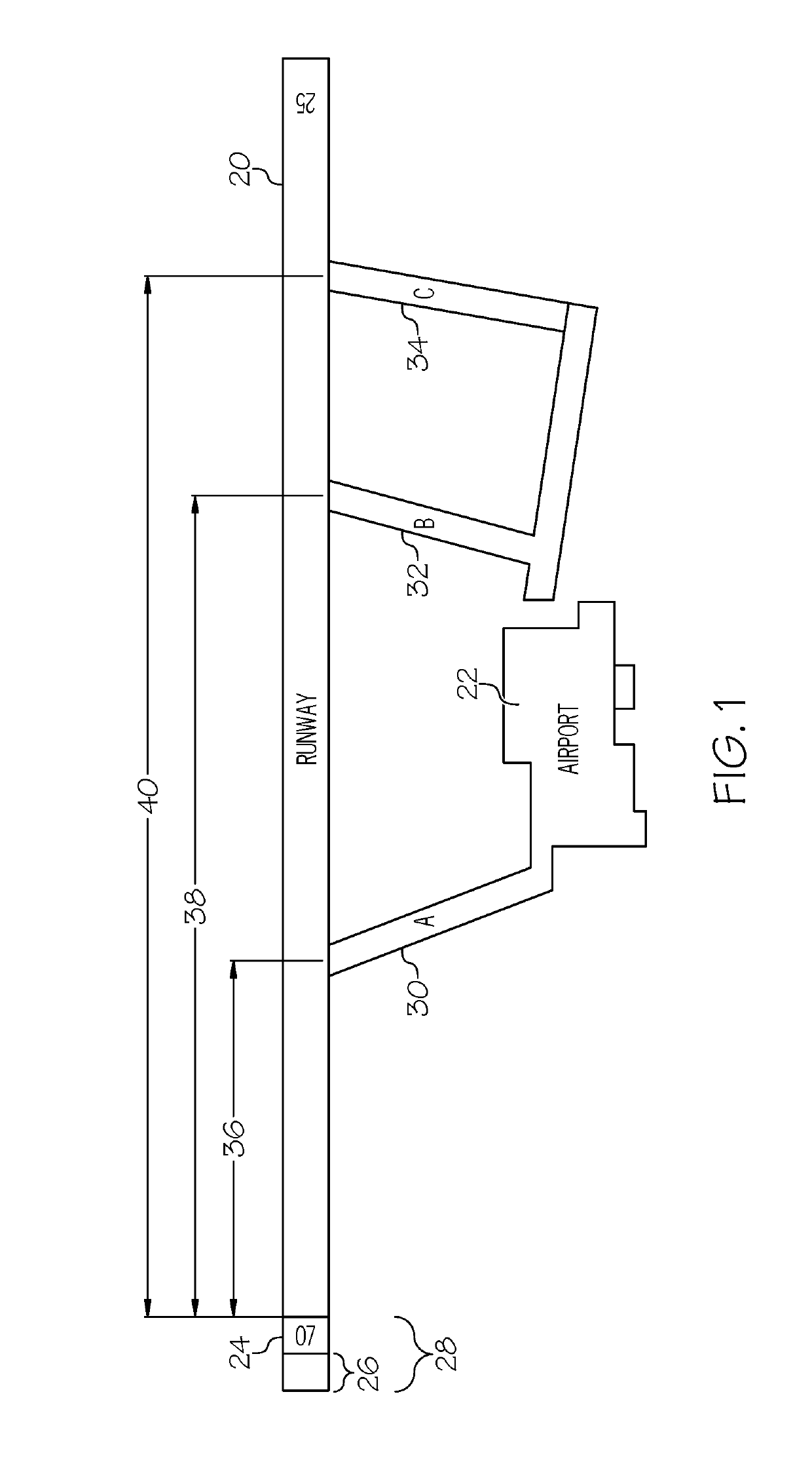
[0016]An example for discussion of optimizing landing performance is shown in FIG. 1. A designated runway 20 at an airport 22 is depicted. The runway identification (ID) 24 is “...


PUM


Abstract

Systems and methods that optimize landing performance are provided. The system determines a number, N, of equipment configurations (a combination of a brake setting and a thrust reverser configuration) supported by the aircraft. The system determines a deceleration airspeed to achieve a target taxi speed and, for each of the N equipment configurations, determines a respective deceleration distance. In various embodiments, the system further updates the deceleration distances by one or more of a brake's condition, aircraft historical data, brake warranty and life cycle data, and environmental conditions. The deceleration distances are used to identify a number P of exit-ways that can be used at the runway. Total costs (including brake usage and fuel cost) for each of the P exit-ways is determined, and the equipment configuration that delivers the lowest total cost delivers the optimize landing performance.

Description

TECHNICAL FIELD[0001]The technical field generally relates to navigational aids, and more particularly relates to identifying an optimized equipment configuration to achieve an optimizing landing performance in an aircraft.BACKGROUND[0002]Landing performance, from a touchdown point to achievement of a target taxi speed, is affected by many parameters. Some of these parameters include weather, winds, runway length and surface conditions. The aircraft's equipment configuration, such as a combination of one or more of an auto brake setting, spoiler setting, landing flap configuration, and a thrust reverser configuration, can also affect landing performance. An optimal landing performance must balance safe landings with factors that affect cost, such as proper maintenance and usage of the components in the relevant equipment.[0003]With respect to brakes, in some instances, a technical problem occurs in that they degrade more quickly than expected, i.e., they do not support as many landi...

Claims


Application Information

Patent Timeline
Patent Type & Authority Patents(United States)
IPC IPC(8): B64C25/42G08G5/02G05D1/00G08G5/00B64D45/04B60T8/17
CPCG08G5/02G08G5/0013G05D1/0083B64D45/04B64C25/426B60T8/1703B64C25/42B60T2210/32B60T2210/36G08G5/025G08G5/0091G08G5/0021
Inventor JAYATHIRTHA, SRIHARIKHAN, KALIMULLARAMACHANDRA, SRIPATHIKIROV, CHAVDARMYLARASWAMY, DINKAR
Owner HONEYWELL INT INC
Why Eureka
Try Eureka