Conversion of solar energy into other forms of useful energy

a technology of solar energy and other forms of useful energy, applied in lighting and heating apparatus, ventilation systems, heating types, etc., can solve the problems of reducing the thermal performance of buildings up to fifty percent, inherent loss of thermal performance, and requiring structural fastening of insulation support apparatuses, etc., to facilitate collection, concentration and storage, and increase the distance between rafters

Active Publication Date: 2019-09-24
HARKINS DANIEL J
View PDF26 Cites 2 Cited by
  • Summary
  • Abstract
  • Description
  • Claims
  • Application Information

AI Technical Summary

Benefits of technology

[0039]A plurality of rigid formed insulation hangers are then attached to the interior facing surface of the first (exterior) wall sheet material. A material insulation layer is attached in substantial contact without the interior-most surface of the first (exterior) wall sheet material using the pre-installed insulation hangers. The material insulation is impaled on the rigid formed insulation hangers designed for this purpose which are completely supported by the exterior wall sheet material and not fastened to the building girts to eliminate thermal bridging to the material insulation layer. A top of each second (interior) wall sheet material is securely attached to the ceiling sheet material, such that it's outer surface is in substantial contact with an inner-most surface of the wall material insulation layer. A bottom of each interior wall sheet material is attached to floor with adhesives, tensioning device, or other suitable attachment means, such that it contacts the wall material insulation layer. The material insulation layer is thereby sandwiched between the first and second wall sheet material layers. The solar heat collecting wall air gap layer is thereby created between an inner surface of the exterior wall panel and the outer surface of the first (exterior) wall sheet material layer.
[0089]It is yet a further object of the present invention to provide an installation system for installing ceiling sheets in buildings, which enables a ceiling sheet to be installed in less time than that of the prior art.

Problems solved by technology

One common problem with the design of current buildings having integrated thermal insulation systems is the requirement for structural fastening of the insulation support apparatus through the plane of the insulation system.
The “through-fastening” creates multiple thermal bridges, which reduces the building thermal performance up to fifty percent.
A second common problem is that insulation products in building roofs and walls are sandwiched between the roof or wall structural members and the overlying building exterior sheeting with compression of the insulation thickness and its inherent loss of thermal performance which results from this compression.
The solar energy that hits the building roof and wall surfaces is lost from any practical collection and use.
The third common problem of achieving energy efficient buildings is that the thermal insulation has traditionally been installed during the roof and wall sheeting process.
This practice severely limits the thermal performance of the buildings to much less than the desirable economic insulation levels.
These structural configurations maximize the uncontrolled heat transfer between the two thermally bridged surfaces on the opposite sides of the thermal insulation layer and will frequently result in seasonal condensation on the interior exposed building structural members.
Buildings that are thermally bridged between through the thermal insulation with exterior exposed conductive sheeting materials and interior exposed conductive roof purlins or joist and exposed conductive wall girts result in the opposite seasonal heat transfer effect that is desired and major loss of heating energy.
This condition results in condensation of the water vapor that increases conductivity and reduces the insulation thermal performance, which may result in permanent building structural damage and may also interfere with the building use.
If the condensed liquid water accumulates within the building roof and wall assemblies it may also result in dripping and damage to interior building contents.
Another problem that occurs in metal panel sheeted buildings is seasonal condensation problems in the wall and roof systems.
This trapped water vapor and resultant liquid water will cause premature deterioration of the building roof and wall building components and will shorten the useful life of the building if it can't escape naturally.
Many older metal buildings leak air or breathe through the eave and wall flashings and the unsealed wall panel joints due to wind pressure differences.
This breathing allowed much of the trapped water vapor to escape, but at the expense of thermal insulation performance.
Buildings that have the compressed thermal insulation, buildings that attempt to fill the roof and wall cavities, buildings that have thousands of staple holes along uniformly spaced insulation facing seams, buildings that have substantially thermally bridged conductive interior and exterior surfaces, buildings that trap and accumulate condensed water vapor within the insulated roof and wall assemblies, and buildings which repel the free solar heat energy hitting its exterior surfaces require significantly greater heating and cooling equipment capacities, require excessive fuel piping, require excessive electrical wiring, require excessive service capacities and cost significantly more to heat, cool and ventilate than would be required, if the above mentioned problems were solved.

Method used


Image

  • Conversion of solar energy into other forms of useful energy
  • Conversion of solar energy into other forms of useful energy
  • Conversion of solar energy into other forms of useful energy

Examples


Embodiment Construction

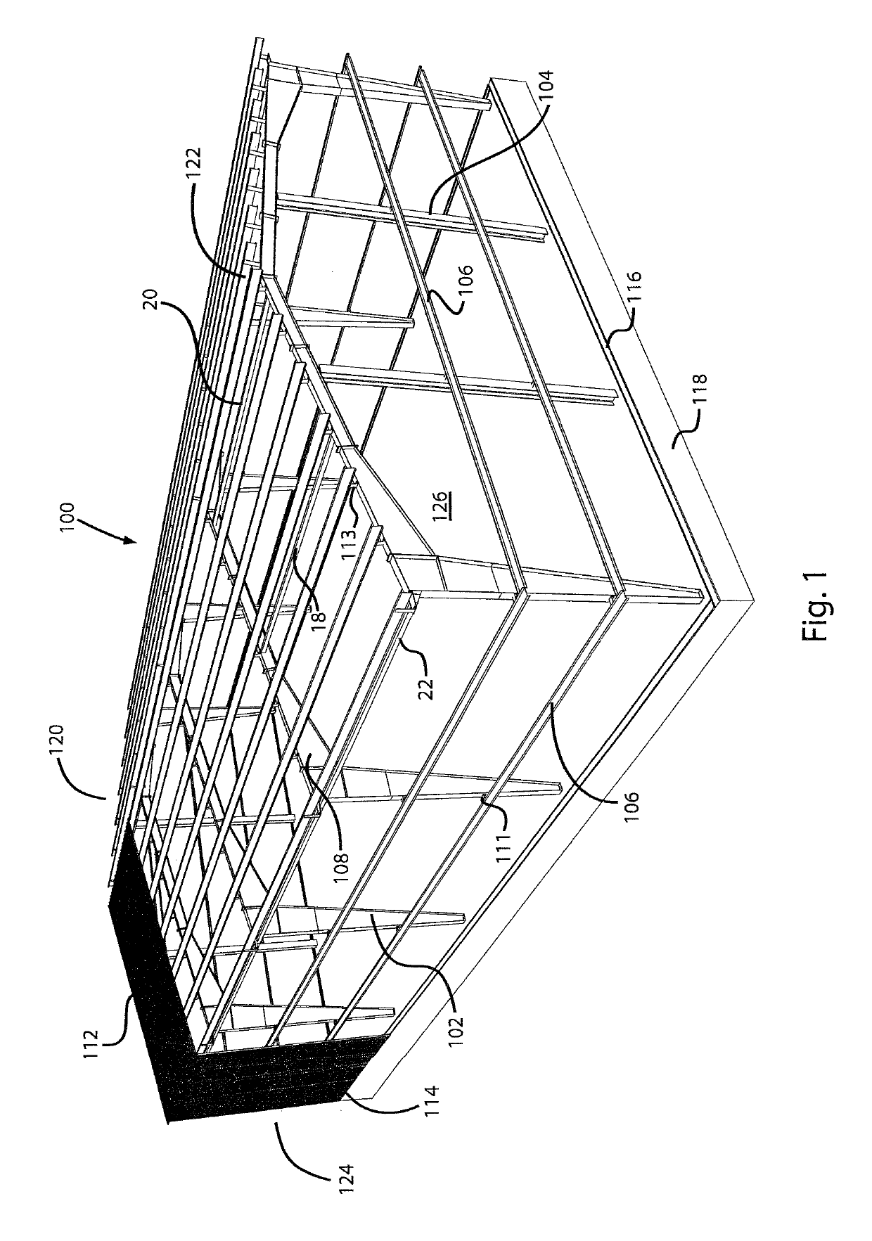
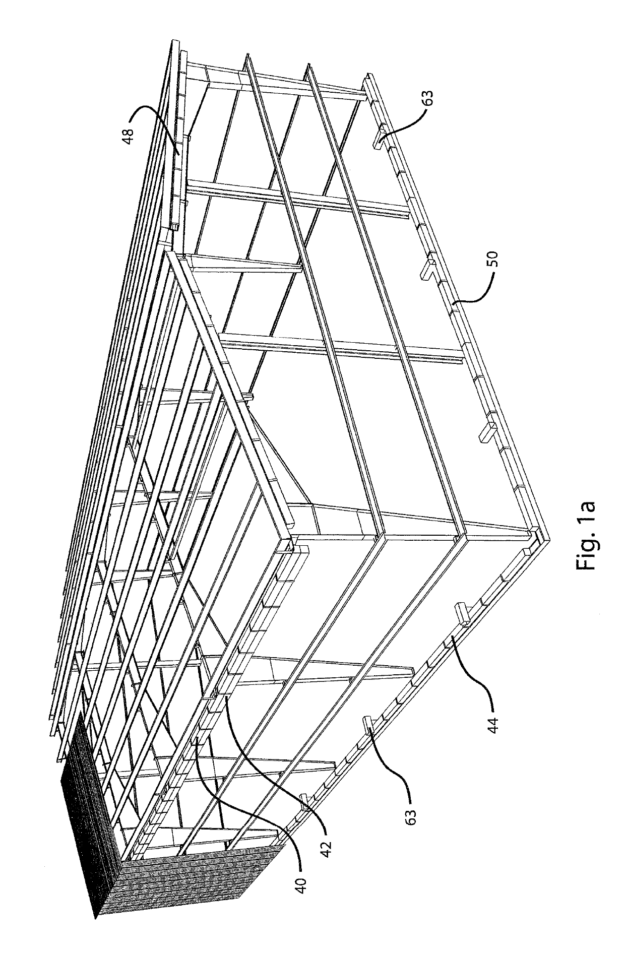
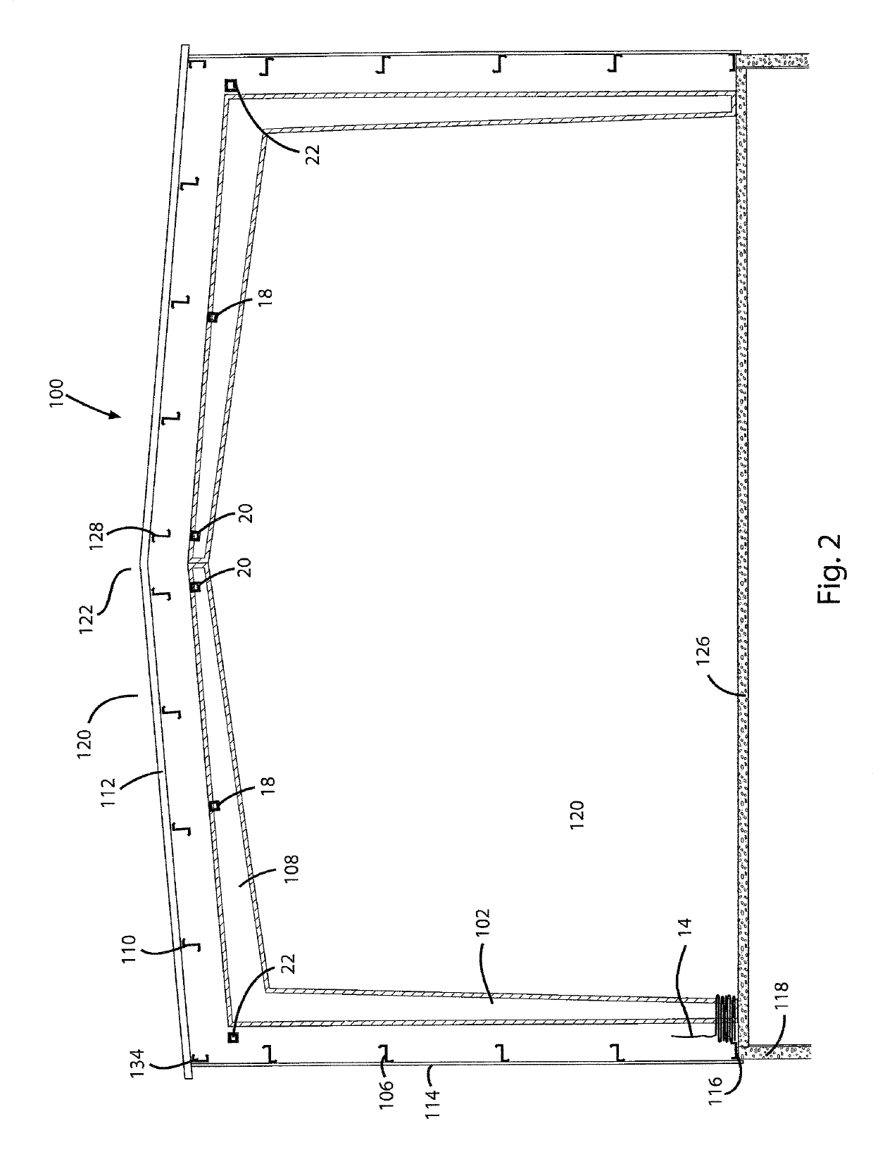
[0168]With reference now to the drawings, and particularly to FIGS. 1 and 10, there is shown a cut-away perspective view of a metal building 100. With reference to FIGS. 10, 11, the metal building 100 preferably includes a heat collection air gap layer 10, 12, air vent spacers 36, 38, an insulation retaining sheet material 14, 30, a material insulation layer 16, 32, 34 and a plurality of ducts 40, 42, 44, 48, 50. The metal building 100 is shown, but other types of buildings may also be used. The metal building 100 includes a plurality of rafter columns 102, a plurality of end columns 104, a plurality of wall girts 106, a plurality of rafters 108, a plurality of purlins 110, 128, 134, a plurality roof exterior sheeting panels 112, a plurality of wall exterior sheeting panels 114 and a peripheral base channel 116. The plurality of rafter columns 102 and the plurality of end columns 104 are attached to the peripheral base foundation 118. The peripheral base channel 116 is attached to a...


PUM


Abstract

An example of conversion of solar energy into other forms of useful energy is taking heat from an area below a roof and using the heat to generate mechanical energy or electrical power. An air duct opening is placed in a hottest area under the roof. An air fan is placed in the air duct to draw the heated air from the area below the roof. A heat exchanger coil is placed inside the air duct. A return air duct is routed back to the area below the roof. The heat exchanger coil is coupled to a turbine through a closed loop line. A heat transfer medium pump, a first valve and a second valve are retained in the closed loop line. The first valve, second valve and pump are used regulate heat transfer medium into and out of the turbine. An electrical generator may be connected to the turbine.

Description

CROSS-REFERENCES TO RELATED APPLICATIONS[0001]This is a continuation-in-part application, which takes priority from application Ser. No. 15 / 248,417, filed on Aug. 26, 2016, which takes priority from application Ser. No. 14 / 838,938, filed on Aug. 28, 2015, which takes priority from application Ser. No. 14 / 553,440, filed on Nov. 25, 2014, which takes priority from application Ser. No. 14 / 270,379, filed on May 6, 2014, now U.S. Pat. No. 8,991,110, which takes priority from application Ser. No. 13 / 616,709, filed on Sep. 14, 2012, now U.S. Pat. No. 8,844,230.BACKGROUND OF THE INVENTIONField of the Invention[0002]The present invention relates generally to utilizing solar energy and more specifically to conversion of solar energy into other forms of useful energy, such as providing mechanical or electrical power.Discussion of the Prior Art[0003]A brochure MB304 published by the North American Insulation Manufacturers Association (NAIMA) continuously since 1991 describes the state of the ar...

Claims


Application Information

Patent Timeline
Patent Type & Authority Patents(United States)
IPC IPC(8): F03G6/00E04B9/04E04F13/00E04B1/342E04B1/24E04D13/16E04B7/00E04B1/76E04B9/30E04B9/24E04D13/17E04D12/00E04D3/36E04B7/02E04B1/74F24S20/67F24S10/30E04B1/41
CPCE04B7/024E04D3/3602E04B1/74E04D13/17E04F13/005E04B1/7675E04B1/7666E04B1/76E04B9/24E04B1/7608E04B1/24E04B9/0414E04D13/1625E04D13/1618E04D12/004E04B9/306E04D12/006E04B7/00F24S10/30F24S20/67E04B1/342E04B2001/2487E04B1/4157Y02B10/20Y02B30/94Y02E10/44E04B2001/2481Y02E10/46Y02B30/90
Inventor HARKINS, DANIEL J.
Owner HARKINS DANIEL J
Why Eureka
Try Eureka