Piezoelectric device, piezoelectric module, and electronic apparatus

a piezoelectric module and piezoelectric technology, applied in the field of piezoelectric modules and electronic devices, can solve the problems of reducing the strength affecting the measurement accuracy of the element substrate, and complicated wiring connections of the ultrasonic transducer, and achieve the effect of high accuracy and measurement accuracy

Active Publication Date: 2019-09-24
SEIKO EPSON CORP
View PDF18 Cites 1 Cited by
  • Summary
  • Abstract
  • Description
  • Claims
  • Application Information

AI Technical Summary

Benefits of technology

[0013]In such a configuration, it is possible to individually control the plurality of connection electrodes by the plurality of through electrodes. In addition, since the through electrodes are configured to be provided in the reinforcement plate rather than being provided in the element substrate, the strength of the element substrate is higher than that in, for example, a configuration in which a through hole or a through electrode is provided in an element substrate, and thus it is possible to suppress damage due to an impact or the like. In addition, although a configuration in which the through electrode is provided in the reinforcement plate is adopted, the reinforcement plate has strength which is sufficiently higher than that of the element substrate, and thus it is possible to suppress the damage of the piezoelectric device. Furthermore, a configuration in which the through electrode is used is adopted, and thus it is also possible to suppress a defect such as a short-circuit, as compared to a configuration in which the connection electrode is connected to a wiring substrate through, for example, wire bonding.
[0031]In the application example with this configuration, the control unit controls the element units, to thereby perform ultrasonic wave transmission and reception processes and to perform measurement (measurement of ultrasonic waves) on an object to be measured, on the basis of transmission and reception timings of the ultrasonic waves. In this application example, as described above, the ultrasonic wave transmission process and the ultrasonic wave reception process in each of the element units can be performed with a high level of accuracy, and thus it is possible to achieve measurement accuracy in the measurement of ultrasonic waves.

Problems solved by technology

However, such a two-dimensional array structure has a problem that wirings connected to the ultrasonic transducers become complicated.
Accordingly, the strength of the element substrate is reduced, which leads to a tendency for the element substrate to be damaged.
However, the above-mentioned cMUT chip is configured such that ultrasonic waves are output by vibrating the second film side, and thus a reinforcement plate cannot be provided on the second film side.
In this case, finally, through electrodes are provided in both the reinforcement plate and the substrate, which results in a problem of the insufficiency of strength.
However, in such a configuration, in the plurality of elements to which the COM and the SIG are common, a voltage drop of a signal occurs in an element distant from an input position of the signal, which results in deterioration in driving accuracy.

Method used


Image

  • Piezoelectric device, piezoelectric module, and electronic apparatus
  • Piezoelectric device, piezoelectric module, and electronic apparatus
  • Piezoelectric device, piezoelectric module, and electronic apparatus

Examples


first embodiment

[0042]Hereinafter, an ultrasonic measurement apparatus as an electronic apparatus of a first embodiment according to the invention will be described with reference to the accompanying drawings.

Configuration of Ultrasonic Measurement Apparatus 1

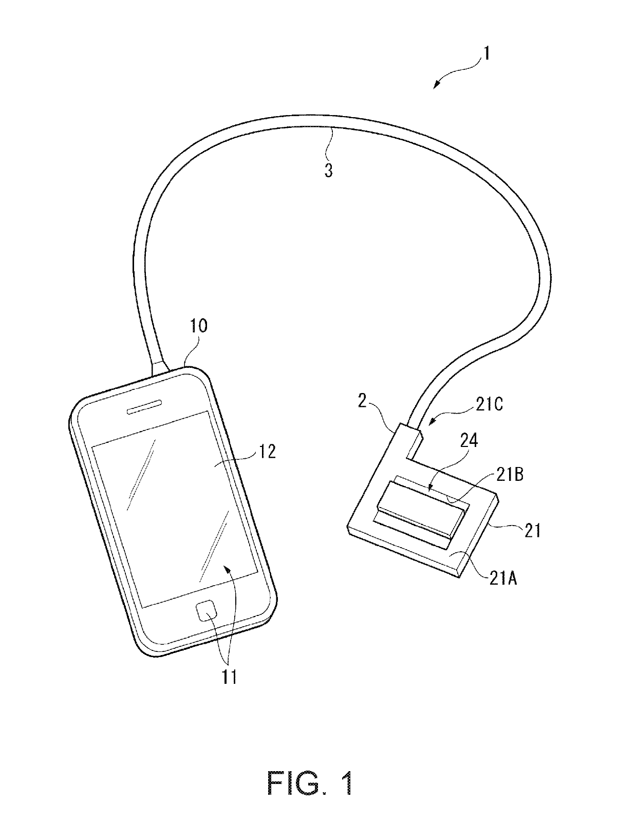
[0043]FIG. 1 is a perspective view showing a schematic configuration of an ultrasonic measurement apparatus 1 according to this embodiment.

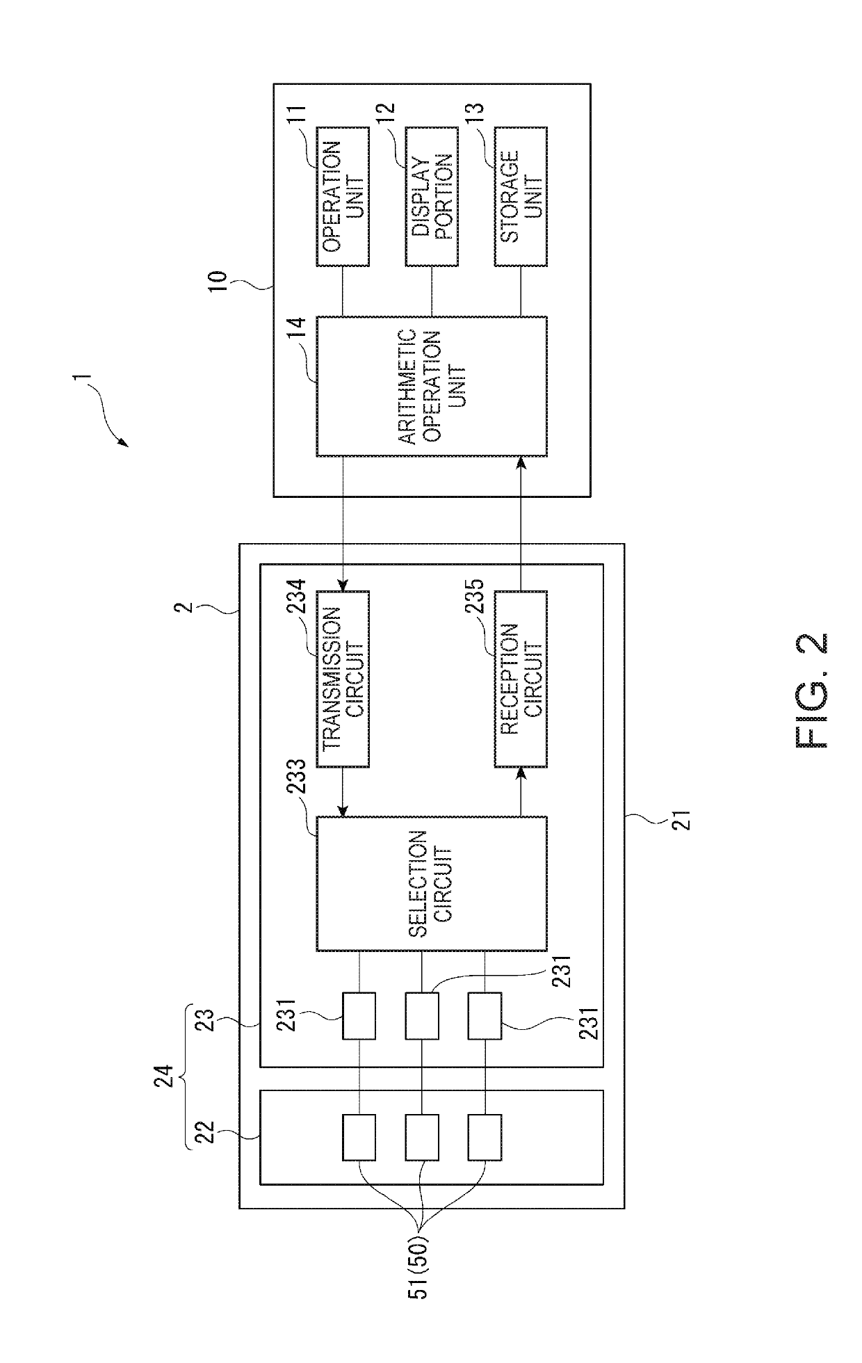
[0044]The ultrasonic measurement apparatus 1 of this embodiment includes an ultrasonic probe 2 and a control device 10 which is electrically connected to the ultrasonic probe 2 through a cable 3, as shown in FIG. 1.

[0045]The ultrasonic measurement apparatus 1 transmits ultrasonic waves into a living body (for example, a human body) from the ultrasonic probe 2 by making the ultrasonic probe 2 abut on the surface of the living body. In addition, the ultrasonic waves reflected by an organ within the living body are received by the ultrasonic probe 2, thereby acquiring, for example, an internal tomographic imag...

second embodiment

[0098]Next, a second embodiment of the invention will be described.

[0099]An ultrasonic measurement apparatus according to this embodiment has substantially the same configuration as that of the ultrasonic measurement apparatus 1 described above, and is different from the ultrasonic measurement apparatus 1 in that a portion of a configuration of a piezoelectric element 413 constituting an ultrasonic transducer is different.

[0100]Meanwhile, in the following description, components that are the same as or substantially the same as those of the ultrasonic measurement apparatus 1 according to the first embodiment will be denoted by the same reference numerals and signs, and a description thereof will be omitted or simplified.

[0101]FIG. 6 is an enlarged plan view of a portion of an element substrate of an ultrasonic sensor of the ultrasonic measurement apparatus according to this embodiment.

[0102]In this embodiment, as shown in FIG. 6, a plurality of ultrasonic transducers 51B mentioned a...

third embodiment

[0108]Next, a third embodiment of the invention will be described.

[0109]An ultrasonic measurement apparatus according to this embodiment has substantially the same configuration as that of the ultrasonic measurement apparatus 1 described above, and is different from the ultrasonic measurement apparatus 1 in that a portion of a configuration of a piezoelectric element 413 constituting an ultrasonic transducer is different.

[0110]Meanwhile, in the following description, components that are the same as or substantially the same as those of the ultrasonic measurement apparatus 1 according to the first embodiment will be denoted by the same reference numerals and signs, and a description thereof will be omitted or simplified.

[0111]FIG. 7 is an enlarged plan view of a portion of an element substrate of an ultrasonic sensor of the ultrasonic measurement apparatus according to the embodiment.

[0112]In this embodiment, as shown in FIG. 7, a plurality of ultrasonic transducers 51C and 51D are d...


PUM


Abstract

A piezoelectric device includes an element substrate that includes a first surface (operating surface) and a second surface (back surface) on a side opposite to the first surface, and includes a recessed opening provided on the first surface and a supporting portion surrounding the recessed opening, a piezoelectric body that is provided on the second surface of the recessed opening, a plurality of connection electrodes (lower connection electrode and upper connection electrode) that are connected to the piezoelectric body and are drawn to the second surface of the supporting portion from the piezoelectric body, a reinforcement plate that is bonded to the second surface side of the element substrate, and a plurality of through electrodes that are provided at a position of the reinforcement plate which faces the supporting portion, pass through the reinforcement plate in a thickness direction, and are respectively connected to the plurality of connection electrodes.

Description

BACKGROUND[0001]1. Technical Field[0002]The present invention relates to a piezoelectric device, a piezoelectric module, and an electronic apparatus.[0003]2. Related Art[0004]In the related art, an ultrasonic sensor including a plurality of ultrasonic transducers mounted on a sensor substrate has been known (for example, JP-A-2012-152319).[0005]The ultrasonic sensor disclosed in JP-A-2012-152319 mentioned above includes, for example, a matrix-like two-dimensional array structure in which four ultrasonic transducers are disposed on the sensor substrate at equal intervals along an X-axis and a Y-axis. However, such a two-dimensional array structure has a problem that wirings connected to the ultrasonic transducers become complicated.[0006]In order to solve the above-described problem, an ultrasonic probe using a through electrode has been known (for example, Pamphlet of International Publication WO 2009 / 139400).[0007]The ultrasonic probe disclosed in Pamphlet of International Publicat...

Claims


Application Information

Patent Timeline
Patent Type & Authority Patents(United States)
IPC IPC(8): A61B8/00H01L41/04H01L41/08H01L41/047B06B1/06
CPCA61B8/44B06B1/0622H01L41/0825H01L41/042A61B8/4494H01L41/0475A61B8/4483A61B8/04A61B8/06A61B8/5269A61B8/56H04R17/00B06B1/0648H10N30/875H10N30/1071H10N30/802
Inventor KIYOSE, KANECHIKA
Owner SEIKO EPSON CORP
Why Eureka
Try Eureka