
Multi-parametric environmental diagnostics and monitoring sensor node

a sensor node and environmental diagnostic technology, applied in the field of environmental quality monitoring and diagnostic systems and methods, can solve the problems of increasing regulatory and economic requirements for monitoring, increasing concerns about the adverse effects of chemical emissions on the environment, and increasing the number of chemical emissions and their impacts

Active Publication Date: 2019-10-01
QATAR UNIVERSITY +1
View PDF15 Cites 5 Cited by
  • Summary
  • Abstract
  • Description
  • Claims
  • Application Information

AI Technical Summary

Benefits of technology

The patent describes a sensor node that can monitor and diagnostics different environmental factors using multiple sensors and sources of renewable energy. The sensor node has a base with an opening and environmental sensors mounted on the base. It also has a power storage module that can be charged by the sensors and an internal photovoltaic cell that is exposed to light from both external and internal sources. The sensor node has a power management system that can selectively charge the supercapacitor from different sources simultaneously. The technical effects of this invention are improved environmental monitoring and diagnostics powered by multiple sources of renewable energy, making it more reliable and efficient.

Problems solved by technology

These chemical emissions and their impacts are numerous and complex.
These emissions have increased concerns about their adverse effects on their surroundings.
These emissions have also resulted in increased regulatory and economic requirements for monitoring and treating the pollution.
Large scale deployment of these conventional sensor devices, however, requires a large number of batteries, which may be toxic for the environment, and a large staff to maintain the sensor nodes for these environmental air quality monitoring systems.

Method used


Image

  • Multi-parametric environmental diagnostics and monitoring sensor node
  • Multi-parametric environmental diagnostics and monitoring sensor node
  • Multi-parametric environmental diagnostics and monitoring sensor node

Examples


Embodiment Construction

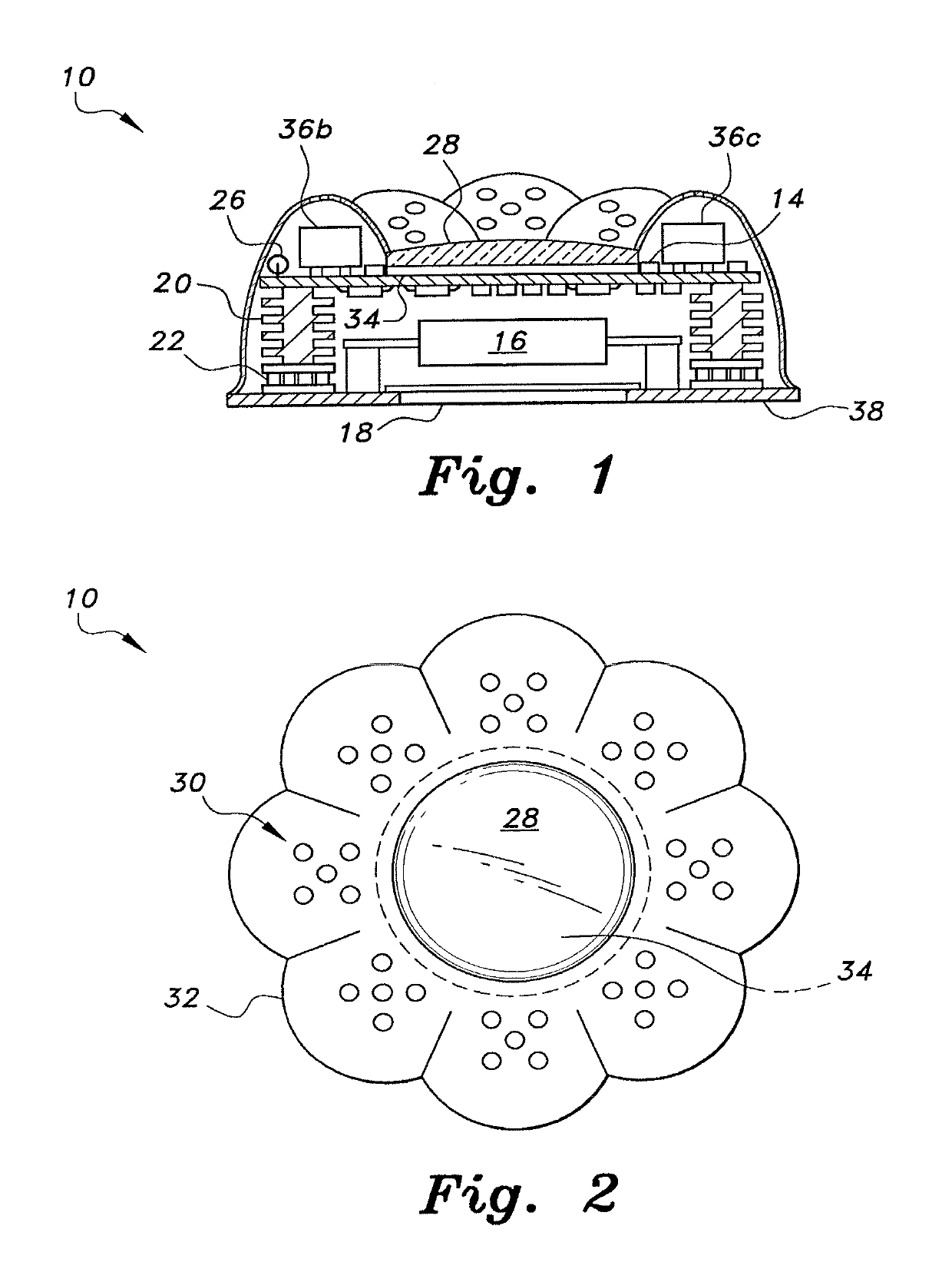
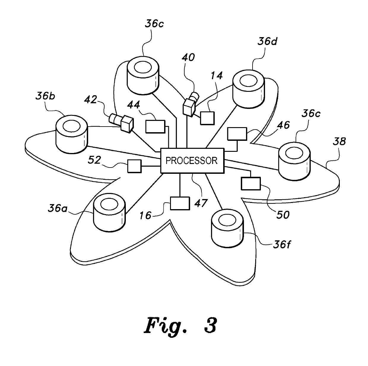
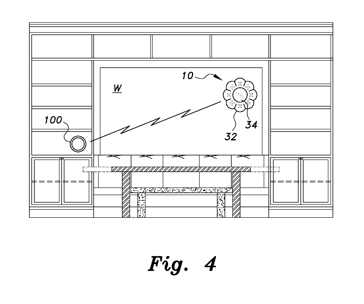
[0019]The multi-parametric environmental diagnostics and monitoring sensor node 10 utilizes a combination of a variety of environmental power sources for powering a variety of different environmental sensors mounted on the node 10. As best shown in FIGS. 1 and 3, the multi-parametric environmental diagnostics and monitoring sensor node 10 includes a plurality of environmental sensors 36a, 36b, 36c, 36d, 36e and 36f operating together in a unitary system. For example, sensor 36a may be an electrochemical gas sensor for detecting and measuring levels of chlorine pollutants in the air, sensor 36b may be an electrochemical gas sensor for detecting and measuring levels of hydrogen sulfide pollutants in the air, sensor 36c may be an electrochemical gas sensor for detecting and measuring levels of carbon monoxide in the air, sensor 36d may be an electrochemical gas sensor for detecting and measuring levels of nitrogen dioxide pollutants in the air, sensor 36e may be an electrochemical gas ...


PUM

PropertyMeasurementUnit
radio frequencyaaaaaaaaaa

Abstract

The multi-parametric environmental diagnostics and monitoring sensor node (10) provides monitoring and diagnostics of a variety of different ambient environmental factors and is powered by multiple sources of renewable energy. The multi-parametric environmental diagnostics and monitoring sensor node (10) includes a base (38) and a plurality of environmental condition sensors (36a, 36b, 36c, 36d, 36e, 36f) mounted thereon. A controller (47) is also mounted on the base (38), the plurality of environmental condition sensors (36a, 36b, 36c, 36d, 36e, 36f) being in communication therewith. An external photovoltaic cell (18) is mounted to the base and an internal photovoltaic cell (34) is mounted in an opposed orientation on a cover (32). The external photovoltaic cell (18) and the internal photovoltaic cell (34) charge a power storage module (52), which powers the plurality of environmental condition sensors (36a, 36b, 36c, 36d, 36e, 36f) and the controller (47).

Description

TECHNICAL FIELD[0001]The present invention relates to environmental quality monitoring and diagnostics systems and methods, and particularly to a multi-parametric environmental diagnostics and monitoring sensor node for environmental air quality monitoring and diagnostics that uses energy harvested concurrently from multiple renewable energy sources to power the sensor node.BACKGROUND ART[0002]The diversity and quantity of chemicals released into the environment has increased dramatically in recent years. These chemical emissions and their impacts are numerous and complex. These emissions have increased concerns about their adverse effects on their surroundings. These emissions have also resulted in increased regulatory and economic requirements for monitoring and treating the pollution. Conventional sensor devices for these emissions are small in size and communicate untethered over short distances. Typically, these conventional sensor devices consist of sensing units, data process...

Claims


Application Information

Patent Timeline
Patent Type & Authority Patents(United States)
IPC IPC(8): G01N33/00G01D21/02G01D11/00G01W1/11H02J7/35H02S40/38G01N27/26H02J7/34G01L19/00
CPCG01N33/004H02J7/355G01N33/0037G01N33/0031G01N33/0054G01N33/0044H02S40/38G01W1/11G01D11/00G01N33/0073G01D21/02G01N27/26G01L19/0092H02J7/345Y02E10/56Y02E70/30H02J7/35
Inventor CRESCINI, DAMIANOTOUATI, FARIDCRESCINI, PAOLOLEGENA, CLAUDIOGALLI, ALESSIOMNAOUER, ADEL BEN
Owner QATAR UNIVERSITY
Learn More