Sensor Network System, Base Station, and Method to Forward Measured Data

a sensor network and sensor technology, applied in the direction of instruments, wireless commuication services, force/torque/work measurement apparatus, etc., can solve the problems of large labor, required change, and large resource burden of wireless network, and achieve the effect of reducing the load of the wireless network having many constraints on resources, facilitating adoption, and enhancing utilization efficiency

Active Publication Date: 2007-09-13
HITACHI LTD
View PDF1 Cites 113 Cited by
  • Summary
  • Abstract
  • Description
  • Claims
  • Application Information

AI Technical Summary

Benefits of technology

[0014]Therefore, in the invention, a rule for the format conversion of measured data received by a base station via the network can be set with respect to each sensor node or each measured data as a conversion setting definition (a profile or plug-in). Hereby, a new type of sensor node and a new protocol can be easily adopted without updating the software of the gateway and the server.
[0015]As the conversion processor transmits measured data to the network after the conversion processor adds semantic information of the measured data when the conversion processor converts unprocessed measured data received from the sensor node to measured data in the text format based upon conversion definition information, a load of the wireless network having many constraints on resources is reduced and the efficiency of the utilization can be enhanced.

Problems solved by technology

However, to join the new type of sensor node and a different type of sensor node in the existing sensor network system, the definition related to the output of the sensor node is required to be changed in all application software and enormous labor is required.
Further, there occurs a problem that every time a new sensor node is joined, a definition related to the output is required to be changed and labor required for the development and the maintenance of application software is enormous.

Method used


Image

  • Sensor Network System, Base Station, and Method to Forward Measured Data
  • Sensor Network System, Base Station, and Method to Forward Measured Data
  • Sensor Network System, Base Station, and Method to Forward Measured Data

Examples


transformed example 1

[0182]As for the measured value conversion plug-in shown in FIG. 3, the example that the output value (a value converted to a decimal number) of the sensor SS is converted to significant information with SI is described, however, as shown in FIG. 19, a conversion table PI1Ta for converting the output value of the sensor SS such as the temperature value conversion plug-in PI1′ and an individual characteristic correction table PI1Tb for compensating an error among the individual sensor nodes based upon the converted measured value may be also provided. Hereby, an error with respect to each individual sensor node is compensated and more precise measured data can be provided.

second embodiment

[0183]FIGS. 20 to 22 show a second embodiment. If an estimated value of a measured value acquired at this time and output from a sensor SS is within an allowable range (an allowable error) when a specific sleep period elapses, a sensor node SN1 to SNn does not transmit the result of measurement and a sensor network server SNS operates an estimated value using the same algorithm as the sensor node SN1 to SNn to be measured data. Hardware of a sensor network system is similar to that in the first embodiment and is different in a control program of the sensor node SN1 to SNn, a profile PF of a base station BST and plug-in of the sensor network server SNS.

[0184]The sensor node SN1 to SNn (hereinafter SN1) is required to be driven for a long time by a battery BAT and therefore, it is desirable that the frequency of radiocommunication requiring large power consumption is possibly reduced.

[0185]Particularly when the sensor SS is a temperature sensor and a humidity sensor, rapid variation d...

third embodiment

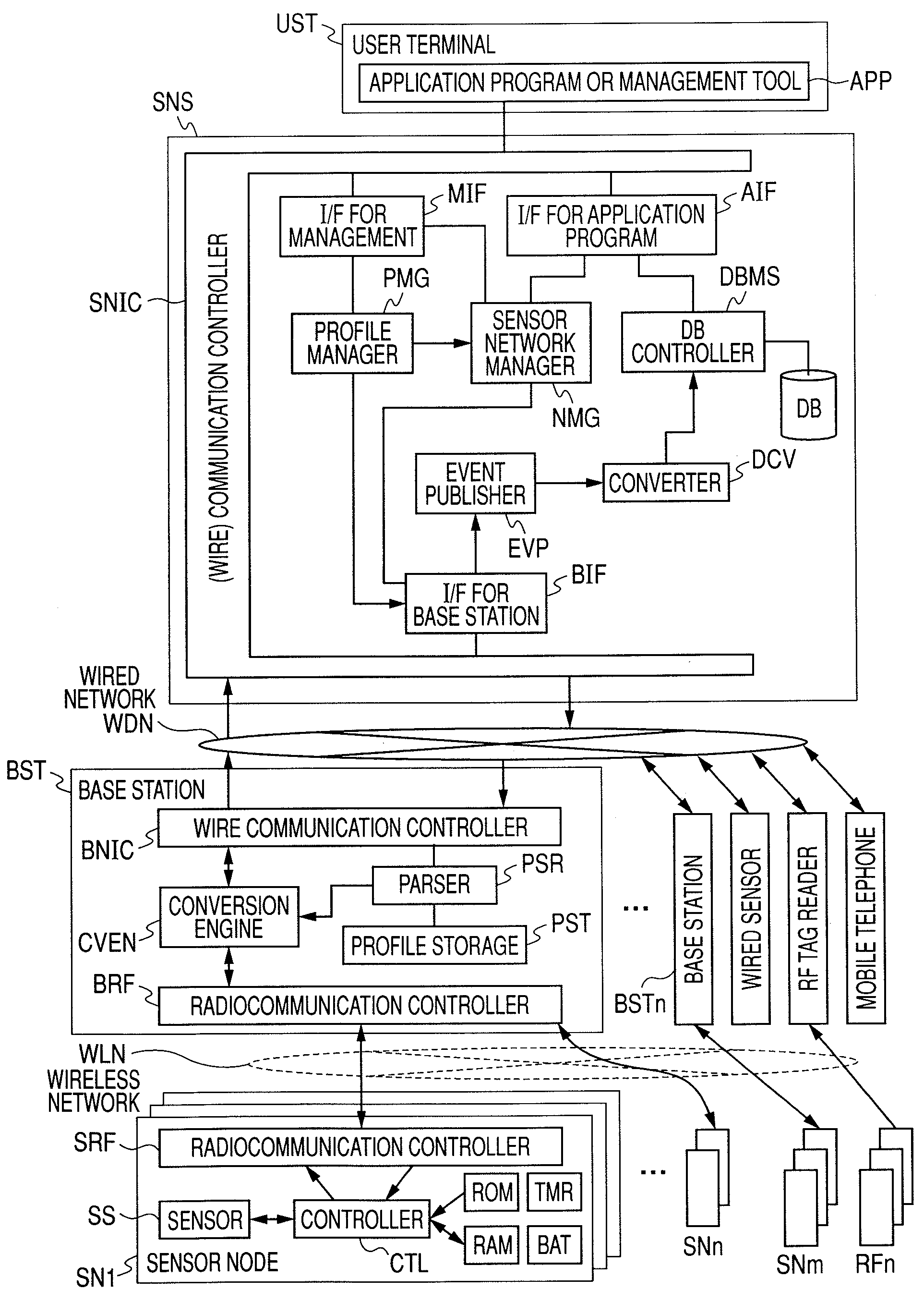
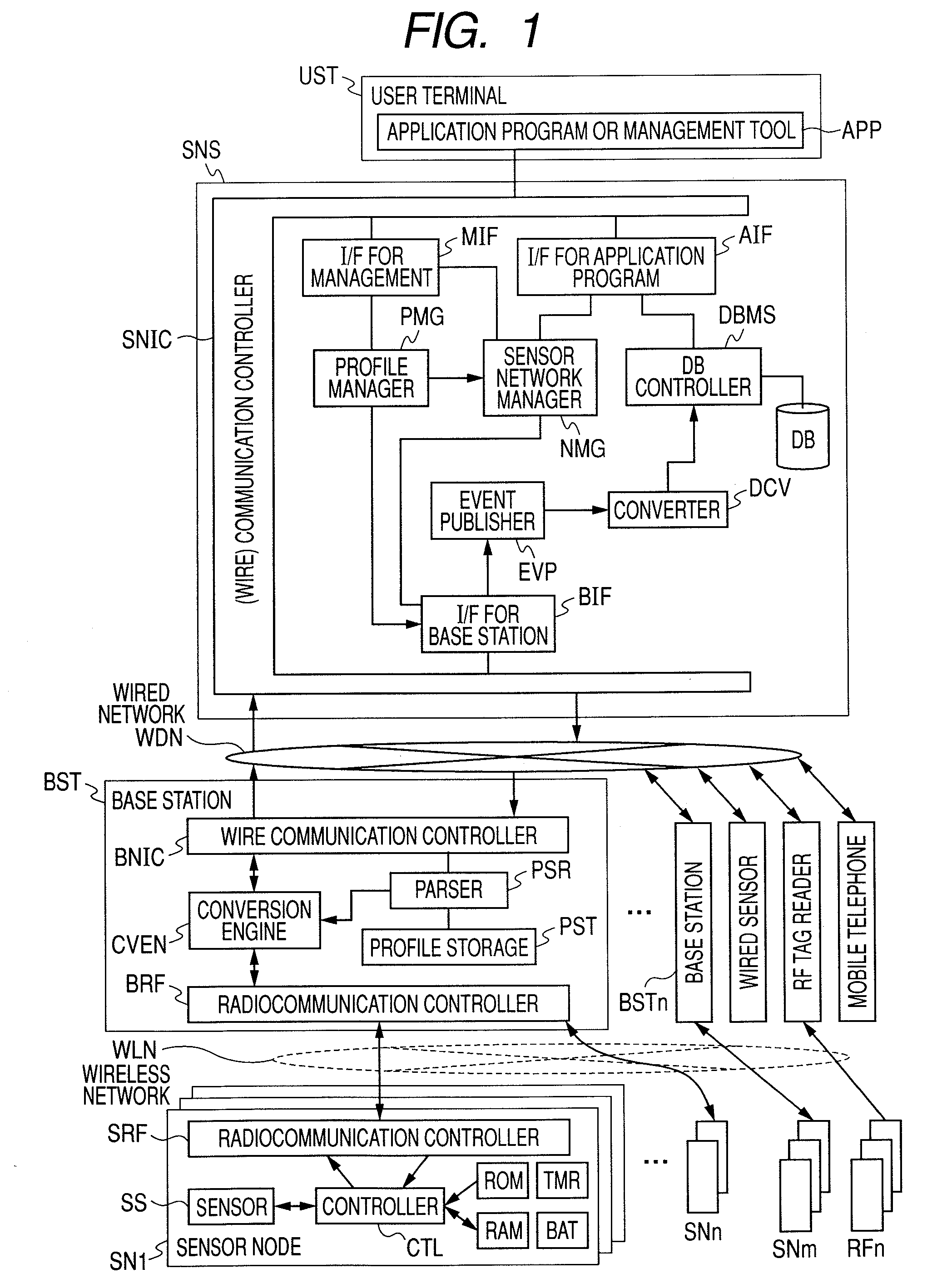
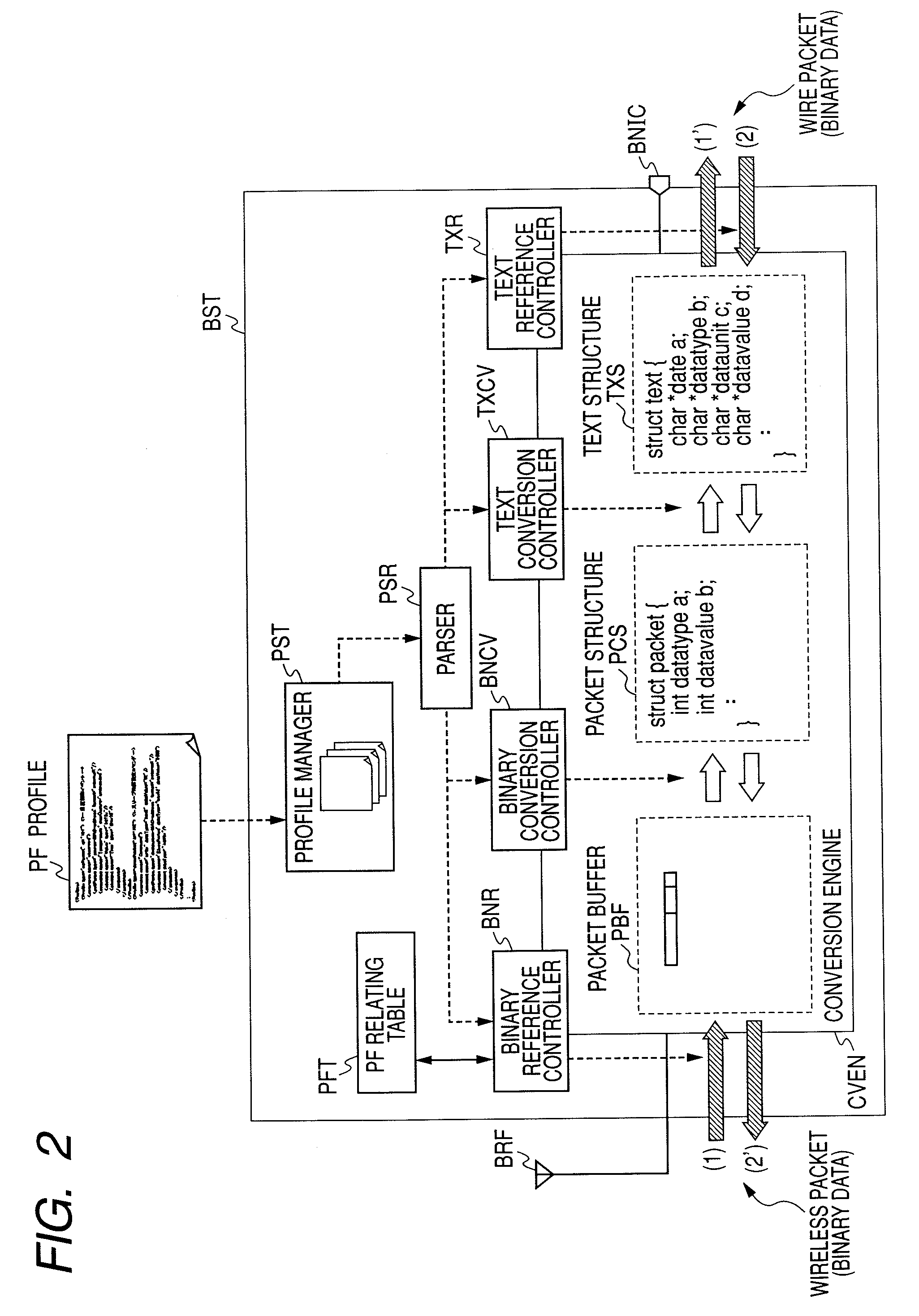
[0222]FIG. 26 shows a third embodiment and shows an example that a conversion engine CVEN utilizing the profile PF described in the first and second embodiments is applied not only to the gateway (the base station BST) in the first and second embodiments but to a sensor network server SNS and a mobile base station as a software adapter.

[0223]A wired sensor node such as an RF ID reader, a camera and a microphone is connected to single or plural sensor network servers SNS via a wired network WDN. The conversion engine CVEN using the profile PF in the first embodiment and a parser PSR are mounted in the sensor network server SNS to utilize measured data transmitted from the wired sensor node SN and the RF ID reader (or writer) in the sensor network server SNS.

[0224]The mobile base station MBST can be configured by building the conversion engine CVEN in the first embodiment or in the second embodiment and the parser PSR in a mobile computer and a mobile telephone as a software adapter. ...


PUM


Abstract

The object of the invention is to facilitate the entry of a new type of sensor node and the adoption of a new protocol in the existing sensor network system effectively utilizing limited resources of radiocommunication. To achieve the object, the following are provided. A sensor node has a radiocommunication unit that transmits a measured value sensed by a sensor and an identifier of a sensor node as binary measured data. A base station has a radiocommunication controller that receives the measured data from the sensor node, a wire communication controller that transmits the received measured data to a server, a conversion definition information selector that selects conversion definition information corresponding to the identifier included in the measured data out of preset plural conversion definition information and a conversion engine that converts the binary measured data to measured data in a text format based upon the selected conversion definition information. The server has a database that stores the measured data in the text format received via a wired network.

Description

CLAIM OF PRIORITY[0001]The present application claims priority from Japanese application JP 2006-061732 filed on Mar. 7, 2006, the content of which is hereby incorporated by reference into this application.FIELD OF THE INVENTION[0002]The present invention relates to technique for utilizing information from multiple sensors connected to a network.BACKGROUND OF THE INVENTION[0003]Recently, a network system where a small-sized electronic circuit having a radiocommunication facility is added to a sensor and various pieces of information in the real world is input to an information processor at real time (hereinafter called a sensor network system) is researched. As for the sensor network system, the wide applications are considered, and for example, technique for regularly monitoring biometric information such as a pulse and positional information by a small-sized electronic circuit acquired by integrating a wireless circuit, a processor, a sensor and a battery, transmitting the result ...

Claims


Application Information

Patent Timeline
Patent Type & Authority Applications(United States)
IPC IPC(8): G08B1/00G08B29/00G08C19/16H04L29/06H04Q9/00H04W4/04H04W4/18
CPCG06Q10/0875
Inventor OGUSHI, MUNORUMURO, KEIROOTA, HIROYUKI
Owner HITACHI LTD
Why Eureka
Try Eureka