Catheter insertion device

a catheter and insertion device technology, applied in intravenous devices, process and machine control, instruments, etc., can solve the problems of serious health complications, premature death, and danger to the affected patient, and achieve the effect of lowering the resisting for

Active Publication Date: 2019-10-08
BECTON DICKINSON & CO
View PDF17 Cites 10 Cited by
  • Summary
  • Abstract
  • Description
  • Claims
  • Application Information

AI Technical Summary

Benefits of technology

[0020]One embodiment of the invention provides a catheter insertion device having a manually operated actuator to actuate the catheter insertion device where a predetermined force is required to move the actuator from a first position where the catheter and insertion needle are in a retracted position. Once the actuator is moved from the first position, the actuator moves toward a second position with a lower resisting force than that required to move or be released from the first position thereby enabling rapid deployment and insertion of the catheter into the patient. The actuator according to one embodiment has a detent that engages a recess in a housing when the actuator is in a first position. The actuator is movable between the first position and a second position where a catheter and insertion needle coupled to the actuator move to a second extended position with respect to the housing. A predetermined force is applied to the actuator to separate the detent from the recess where the required force is greater than a force needed to move the actuator to the second position so that the catheter and insertion needle quickly penetrate the skin of a patient.

Problems solved by technology

Diabetes can be dangerous to the affected patient if it is not treated, and it can lead to serious health complications and premature death.
However, maintaining proper diabetes management may be complicated because it has to be balanced with the activities of the diabetic patient.
But one problem with configuring the insertion mechanism to insert the cannula perpendicular to the surface of the skin is that this may increase the overall height of the insertion mechanism, and therefore of the patch pump itself.
The main problem with configuring the insertion mechanism to insert the cannula perpendicular to the surface of the skin is that this may likely increase the overall height of the insertion mechanism, and therefore the patch pump, itself.
However, incorporating such a device into a patch pump would not only add considerably bulk, complexity and cost, but would greatly increase the height of the patch pump.

Method used


Image

  • Catheter insertion device
  • Catheter insertion device
  • Catheter insertion device

Examples


Embodiment Construction

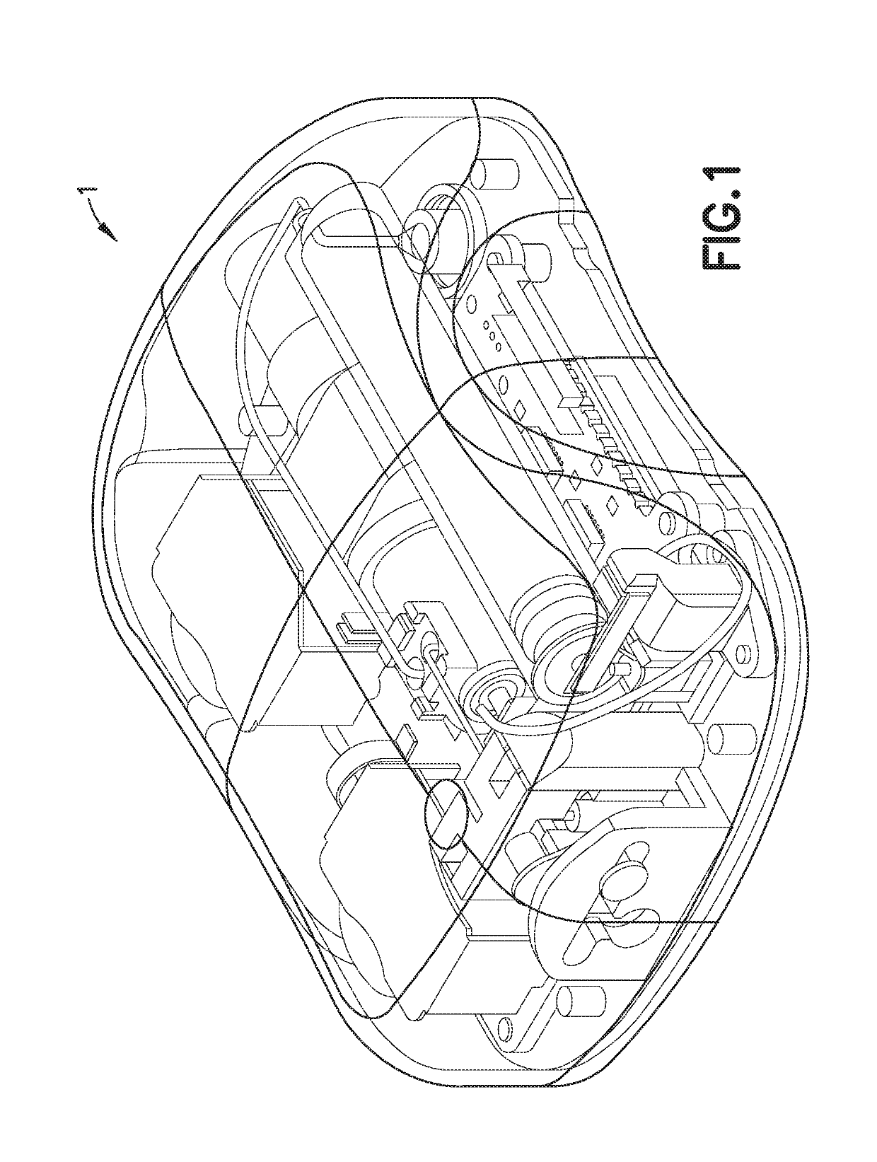
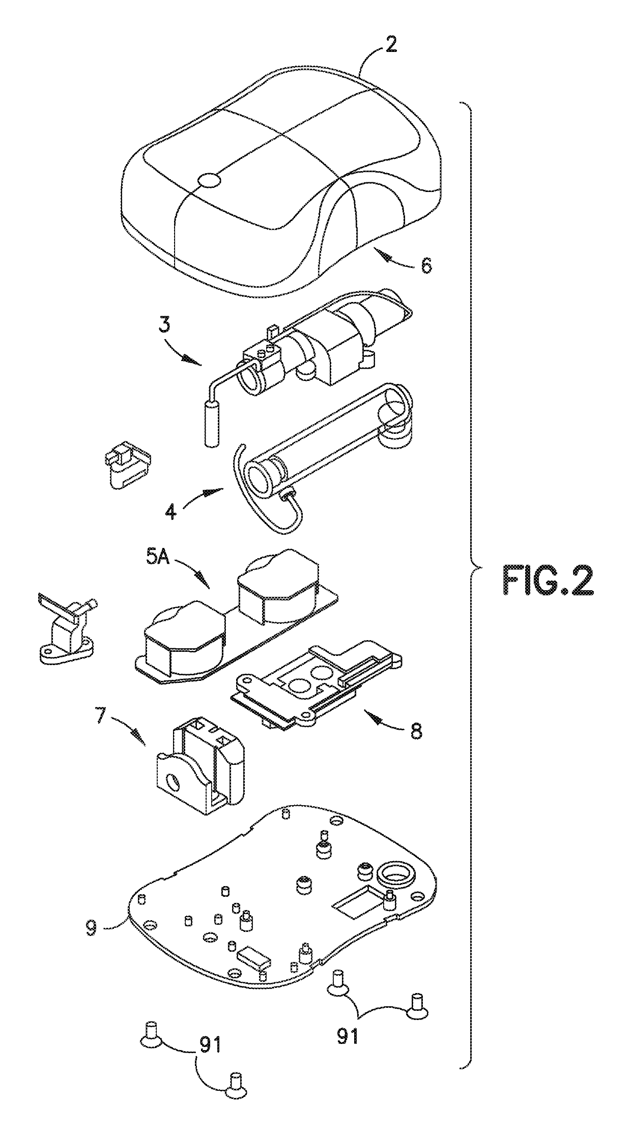
[0038]FIG. 1 is a perspective view of an exemplary embodiment of a patch pump 1 according to an exemplary embodiment of the invention. The patch pump 1 is illustrated with a see-through cover for clarity and illustrates various components that are assembled to form the patch pump 1. FIG. 2 is an exploded view of the various components of the patch pump of FIG. 1, illustrated with a solid cover 2. The various components of the patch pump 1 may include: a reservoir 4 for storing insulin; a pump 3 for pumping insulin out of the reservoir 4; a power source 5 in the form of one or more batteries; an insertion mechanism 7 for inserting an inserter needle with a catheter into a user's skin; control electronics 8 in the form of a circuit board with optional communications capabilities to outside devices such as a remote controller and computer, including a smart phone; a dose button 6 on the cover 2 for actuating an insulin dose, including a bolus dose; and a base 9 to which various compone...


PUM


Abstract

A catheter insertion device (18) includes a housing (12) with a base (14), a catheter (28), an introducer needle (30) and an actuator (26) mounted within the housing. The catheter (28) and needle (30) are coupled to the actuator (26) and movable between a first position where the catheter and needle are retracted within the housing and a second position where the catheter and needle extend from the housing, and where the needle retracts into the actuator when the catheter and needle reach the second position. The actuator (26) has a detent (84) that engages a first recess (76) to require a predetermined force to depress the actuator (26) which is greater than the force necessary to slide the actuator (26) to the second position where the detent (84) engages a second recess (80) in the housing (12) to hold the actuator in the deployed position.

Description

CROSS-REFERENCE TO RELATED APPLICATION[0001]This application claims priority under 35 USC § 119(e) from U.S. Provisional Patent Application Ser. No. 61 / 983,983 filed on Apr. 24, 2014, the disclosure of which is incorporated herein by reference in its entirety.FIELD OF THE INVENTION[0002]The present invention is directed to a catheter insertion device for use in a patch pup or infusion set and to a method of inserting a catheter into a patient using the catheter insertion device. The invention is directed to a catheter insertion device for use with a patch pump, infusion set or other delivery device for introducing a catheter into a patient and automatically retracting an insertion needle once the catheter is moved to an extended position. The invention, in another embodiment, is directed to a manually operated catheter insertion device where a predetermined force is required to actuate the device to provide rapid penetration of the catheter into the patient.BACKGROUND OF THE INVENTI...

Claims


Application Information

Patent Timeline
Patent Type & Authority Patents(United States)
IPC IPC(8): A61M5/142A61M5/168
CPCA61M5/14248A61M2005/16863A61M2005/14252
Inventor COLE, RUSSELLCREIGHTON, MICHAELKLOTZ, ARTHUR
Owner BECTON DICKINSON & CO
Why Eureka
Try Eureka