Spinal tissue ablation apparatus, system, and method

a spinal tissue and apparatus technology, applied in the field of spinal tissue ablation apparatus, system and method, can solve the problems of long treatment time, lack of precise control of power level and temperature, and existing electrode ablation devices, so as to reduce the heat of ablation, increase the coolant flow, and reduce the flow of electric current.

Active Publication Date: 2019-10-15
MEDTRONIC HLDG CO SARL
View PDF42 Cites 2 Cited by
  • Summary
  • Abstract
  • Description
  • Claims
  • Application Information

AI Technical Summary

Benefits of technology

[0017]In accordance with one preferred embodiment of the invention, the system further includes a power generator. The power generator includes, among other things, a detector, a touch screen display, a control module, a human interface panel, and impedance detection / nerve stimulation (“IMP / STM”) switch. In some embodiments, the power generator also may include an RF transmitter / receiver. The detector is configured to receive the spinal tissue temperatures measured by the first, second, and third thermocouples, and to receive the spinal tissue impedance measured by the at least one sensor. The detector is further configured to transmit the spinal tissue temperatures and the spinal tissue impedance to the touch screen display, which is visible to the surgeon performing the spinal tissue ablation process. The human interface panel allows the surgeon to control the ablation apparatus, based on his professional judgment in view of the feedback on the touch screen display.
[0019]Likewise, the surgeon may decrease ablation heat by reducing electric current flow to the resistive heating elements, or by increasing coolant flow through the cooling system in the interior space of the housing.

Problems solved by technology

Existing electrode ablation devices, whether monopolar or bipolar devices, and their associated systems, however, lack precise control of power level and temperature; require overly-long treatment times; often inadvertently ablate healthy spinal tissue adjacent to the unhealthy spinal tissue; are insufficiently flexible to reach all locations of unhealthy spinal tissue in the disc space; and provide the surgeon with inadequate control over the ablation procedure.

Method used


Image

  • Spinal tissue ablation apparatus, system, and method
  • Spinal tissue ablation apparatus, system, and method
  • Spinal tissue ablation apparatus, system, and method

Examples


Embodiment Construction

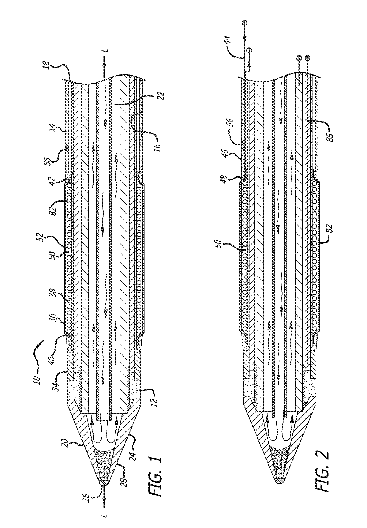
[0036]In accordance with one preferred embodiment of the present invention, and as broadly depicted in FIG. 1, a spinal tissue ablation apparatus 10 is provided for ablating unhealthy spinal tissue.

[0037]In accordance with the invention, the spinal tissue ablation apparatus 10 includes an elongated housing 12. Housing 12 includes an outer surface 14, an inner surface 16, a proximal end 18, and a distal end 20. The inner surface 16 defines an interior space 22. A mid-longitudinal axis L-L is defined between the proximal end 18 and the distal end 20. As used herein, the term “in the proximal direction” refers to movement toward the proximal end 18, whereas the term “in the distal direction” means movement toward the distal end 20. As depicted in FIG. 1, the housing 12 has a cylindrical configuration, but the invention is not limited to a housing having this configuration.

[0038]In accordance with the invention, an anode 24 is defined on the outer surface 14 at the distal end 20. As dep...


PUM


Abstract

Flexible apparatus for ablating unhealthy spinal tissue. A housing includes a distal end and a proximal end. Multiple thermocouples mounted on the housing measure spinal tissue temperatures at locations between the proximal end and the distal end. A sensor measures spinal tissue impedance. The measured spinal tissue impedance corresponds to various physical state data of the spinal tissue. The spinal tissue impedance and the spinal tissue temperatures are displayed to the surgeon, enabling the surgeon to determine with certainty the location of the unhealthy spinal tissue, and to exercise control over the ablation apparatus. Nerve stimulation by IMP / STM switch system to detect nerve responses before and after treatment.

Description

BACKGROUND OF THE INVENTION[0001]Field of the Invention[0002]The present invention relates to an apparatus, a system, and a method for ablating unhealthy spinal tissue, particularly unhealthy and spinal nerve tissue in a disc space between two adjacent vertebral bodies.[0003]Description of the Related Art[0004]Devices and methods for ablating unhealthy spinal tissue in a patient, particularly unhealthy spinal nerve tissue in a disc space between two adjacent vertebral bodies are known. Existing electrode ablation devices, whether monopolar or bipolar devices, and their associated systems, however, lack precise control of power level and temperature; require overly-long treatment times; often inadvertently ablate healthy spinal tissue adjacent to the unhealthy spinal tissue; are insufficiently flexible to reach all locations of unhealthy spinal tissue in the disc space; and provide the surgeon with inadequate control over the ablation procedure.SUMMARY OF THE INVENTION[0005]It is an ...

Claims


Application Information

Patent Timeline
Patent Type & Authority Patents(United States)
IPC IPC(8): A61B18/00A61B18/10A61B18/08
CPCA61N1/36017A61B18/082A61B18/10A61B2018/00023A61B2018/00339A61B2018/00577A61B2018/0072A61B2018/00744A61B2018/00797A61B2018/00821A61B2018/00875A61B5/053A61B2018/00571A61B2018/00011A61B2018/00041A61B2018/00642
Inventor LEE, STEPHEN W.SMITH, MICHAEL A.DUEIRI, DAWUD F.
Owner MEDTRONIC HLDG CO SARL
Why Eureka
Try Eureka