
Method for electrodeposition on a conductive particulate substrate

Active Publication Date: 2019-10-15
BAE SYSTEMS PLC
View PDF16 Cites 0 Cited by
  • Summary
  • Abstract
  • Description
  • Claims
  • Application Information

AI Technical Summary

Benefits of technology

The patent text discusses a method to improve the performance of a battery by concentrating the electrically conductive particulate substrate near the cathode while reducing their dispersion in the electrolyte. This is achieved by using a separator in a biphasic system, which can be achieved by adding a non-ionic surfactant to the organic liquid phase. This method can help to reduce particle agglomeration and improve the performance of batteries.

Problems solved by technology

The problem however, is that in order to establish such an electrical connection:(i) the particulate substrates should be electrically conductive (i.e. can conduct electrons); and(ii) a method is required that confines the electrically conductive particulate substrate proximate to the cathode thereby increasing the concentration of the particulate substrate at the cathode, to reduce the dispersion of the particulates into a larger volume of the surrounding electrolyte.

Method used


Image

  • Method for electrodeposition on a conductive particulate substrate
  • Method for electrodeposition on a conductive particulate substrate
  • Method for electrodeposition on a conductive particulate substrate

Examples


Embodiment Construction

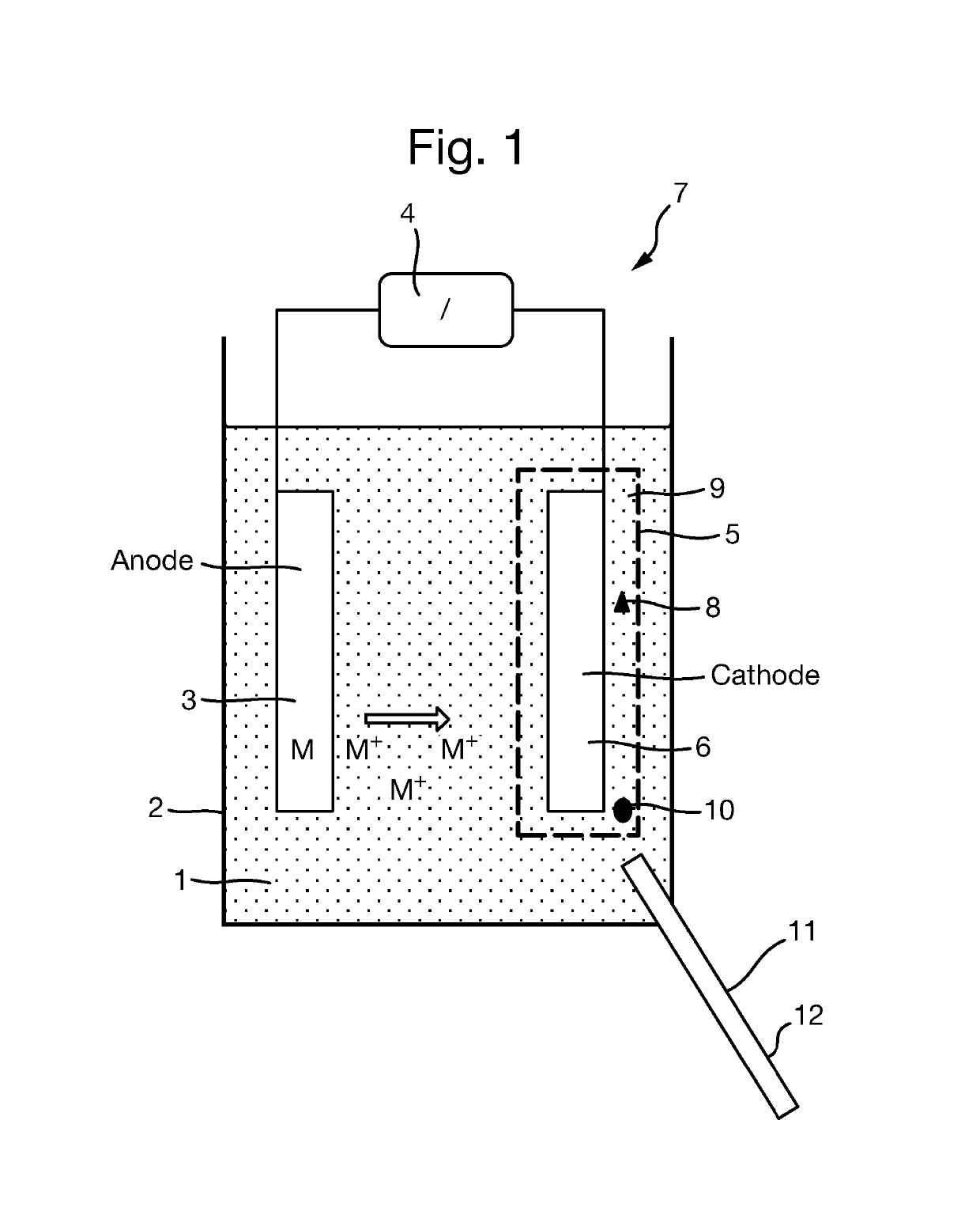
[0061]Turning to FIG. 1, there is provided a batch electrodeposition system 7. The anode 3 which is formed from the metal to be electrodeposited, and cathode 6 are both connected to a power source 4. The electrical circuit is completed by immersing both anode 3 and cathode 6 in an electrolyte 1 housed within an electrodeposition bath 2. The electrolyte 1 allows the free movement of metal ions M+ generated from the anode 3, which migrate to the cathode 6. A separator 9 in the form of a semipermeable membrane 5 substantially envelopes the cathode 6 and the electrically conductive particulate substrate 8. The semipermeable membrane 5 is porous to the electrolyte 1 and metal ions M+, but with a pore size sufficiently small enough to confine the particulate substrate 8 proximate to the cathode 6. The semipermeable membrane 5 reduces dispersion of the particulate substrate 8 into the larger volume of electrolyte 1. Activating the power source 4 sets up a voltage between the anode 3 and ca...


PUM

PropertyMeasurementUnit
Lengthaaaaaaaaaa
Electrical conductivityaaaaaaaaaa
Magnetic fieldaaaaaaaaaa

Abstract

The present invention relates to a method of electrodepositing a metal on an electrically conductive particulate substrate. There is provided a method of electrodepositing a metal on an electrically conductive particulate substrate comprising the steps of: (i) providing a cathode; (ii) providing an anode formed from the metal to be electrodeposited; (iii) providing the substrate, cathode and anode within an electrodeposition bath comprising an electrolyte; and (iv) providing a voltage between said anode and cathode causing metal ions to flow from the anode to the cathode, wherein a separator is provided between the anode and the cathode.

Description

RELATED APPLICATIONS[0001]This application is a national phase application filed under 35 USC § 371 of PCT Application No. PCT / GB2015 / 050456 with an International filing date of Feb. 18, 2015 which claims priority of GB Patent Application 1414431.5 filed Aug. 14, 2014. Both of these applications are herein incorporated by reference in its entirety for all purposes.FIELD OF THE INVENTION[0002]The present invention relates to a method of electrodepositing a metal on an electrically conductive particulate substrate.BACKGROUND OF THE INVENTION[0003]Galvanic electrodeposition is a well-known methodology primarily used for the deposition of high quality metallic films with controllable thickness, forming objects by electroforming and altering the surface properties of an object such as; abrasion and wear resistance, corrosion protection, lubricity, magnetic resistance and conductivity and aesthetic qualities amongst others. Electrodeposition is generally understood to mean the precipitati...

Claims


Application Information

Patent Timeline
IPC IPC(8): C25D7/00C25D3/20C25D21/10C25D17/00C25D5/00
CPCC25D7/006C25D17/002C25D21/10C25D5/009C25D3/20
Inventor DYKE, AMY ELIZABETHDUNLEAVY, MICHAEL
Owner BAE SYSTEMS PLC
Learn More