Linear motor with electric current injection assembly with springs connected to movable coil inside a mass block and upper and lower stationary magnets

a technology of linear motors and mass blocks, applied in the direction of dynamo-electric machines, electrical equipment, supports/enclosements/casings, etc., can solve the problems of difficult arrangement of magnets mounted on mass blocks, loss of vibration function of motors, etc., to achieve no noise, improve vibration stability, and facilitate miniaturization of linear motors

Active Publication Date: 2019-10-15
JINLONG MACHINERY & ELECTRONICS CO LTD
View PDF23 Cites 17 Cited by
  • Summary
  • Abstract
  • Description
  • Claims
  • Application Information

AI Technical Summary

Benefits of technology

[0014]The linear motor further comprises a second fasten plate, the movable plate being located between the second fasten plate and the mass block, and the second fasten plate is fastened by fitting onto the mass block so as to prevent the movable plate from slipping off.
[0028]4. In the linear motor provided by the present invention, the movable plate is a flexible plate so as to protect the coil from being damaged. Furthermore, even if slight vibration of the coil in the vertical direction is caused by a manufacture error, such vibration can be buffered and absorbed by the flexible plate, and thus no noise is generated. In addition, the movable plate as a flexible plate can allow compression deformation, which is favorable for mounting another plate on the outer side of the movable plate to further secure the positioning of the movable plate on the mass block. The movable plate as a flexible plate can buffer slight vibrations caused by external environment during use of the motor, so that the third contactor on the first fasten plate can steadily conduct electric current in and out of the motor.

Problems solved by technology

This type of structure is generally called a “moving-magnet” structure, but it has a major disadvantage: when the magnetic induction line of the magnet directly faces the coil and is perpendicular to the coil, the generated electromagnetic force is parallel to the bottom plate, and thus the coil is driven by electromagnetic force to move parallel to the bottom plate; however, because the magnetic induction line generated by the magnet is arc-shaped, when the magnet moves to either of the two lateral sides, the magnetic induction line is not perpendicular to the coil, and thus the generated electromagnetic force has a horizontal force component parallel to the bottom plate of the housing as well as a vertical force component perpendicular to the bottom plate of the housing, wherein the vertical force component causes the magnet to move in a vertical direction of the housing.
The vertical direction refers to the thickness direction of the housing, along which the thin-type linear motor has a smallest dimension with very narrow space, and as a result, the suspension component collides with the housing in its vertical motion and causes noise.
In a situation of severe attraction force, the vibrator would be “stuck to” the housing surface, causing vibration failure of the motor that loses vibration function.
However, the shield plate itself has high magnetic conductivity and tends to attract the magnet within the suspension component.
The two shield plates on both sides of the suspension component simultaneously attract the suspension component, and it is very difficult for the magnet mounted on the mass block to be arranged such that the attraction forces of the two shield plates towards the vibrator's magnet are exactly equal, therefore, in a situation of uneven force, the suspension component would move in the thickness direction of the housing and thus collide with the housing.

Method used


Image

  • Linear motor with electric current injection assembly with springs connected to movable coil inside a mass block and upper and lower stationary magnets
  • Linear motor with electric current injection assembly with springs connected to movable coil inside a mass block and upper and lower stationary magnets

Examples


embodiment 1

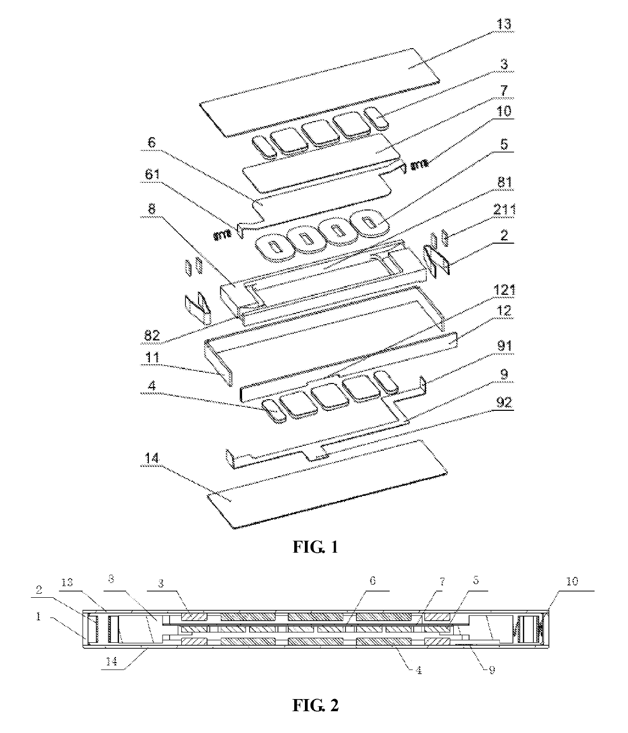
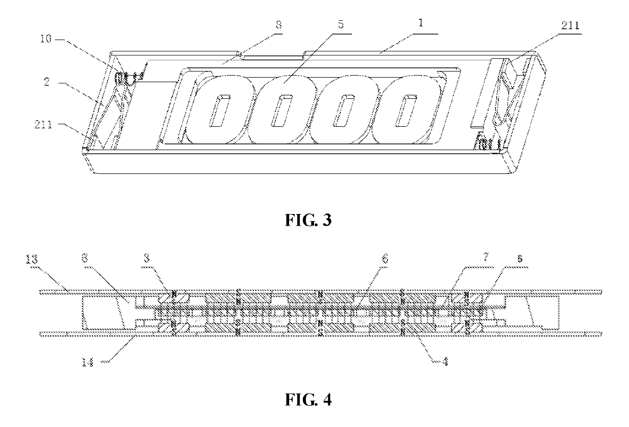
[0042]A linear motor, comprises a housing 1 having an accommodation space; a mass block 8 suspended in the accommodation space of the housing 1 by an elastic member 2; a coil 5 fastened on the mass block 8; and a magnet component comprising a first magnet and a second magnet that have opposite magnetic poles and are symmetrically disposed at an upper side and at a lower side relative to the coil 5 in the middle and positioned parallel to the centric plane of the coil 5. When the coil 5 is energized, the electromagnetic interaction between the coil 5 and the magnet component generates an electromagnetic force to drive the mass block 8 with the coil 5 to vibrate back and forth in a substantially horizontal direction.

[0043]In the above-mentioned linear motor, the design route that utilizes the motion of the coil 5 to drive the motion of the mass block 8, is different from the traditional route that utilizes magnet motion to drive mass block motion. As shown in FIG. 1 or FIG. 4, when th...


PUM


Abstract

The present invention provides a linear motor, wherein, a coil is fastened on a mass block that is suspended inside a housing, a first magnet and a second magnet that have opposite magnetic poles are symmetrically disposed at an upper side and at a lower side relative to the coil in the middle and positioned parallel to the centric plane of the coil, by arranging an upper magnetic steel and a lower magnetic steel at an upper side and at a lower side relative to the mass block in the middle and parallel to the mass block. In the linear motor of the present invention, the design route that utilizes coil motion to drive mass block motion is different from the traditional route that utilizes magnet motion to drive mass block motion. When the coil moves to either of the two lateral sides of the housing, both the first magnet and the second magnet simultaneously generate forces along a vertical direction of the housing, and as the first magnet and the second magnet having opposite magnetic poles are symmetrically disposed on both sides of the coil, the electromagnetic forces generated by the two magnets are equal in magnitude and opposite in direction, thus being counterbalanced with each other in the vertical direction, so as to ensure that the coil only moves back and forth in a horizontal direction, without generating vibration in a vertical direction, therefore, no noise related to vertical vibration is caused.

Description

CROSS REFERENCE[0001]This application is based upon and claims priority to Chinese Patent Application No. 201610187267.5 filed on Mar. 29, 2016 and titled “A LINEAR MOTOR”, the entire content of which is incorporated herein by reference.TECHNICAL FIELD[0002]The present invention relates to a horizontal vibration micro motor, which pertains to the technical field of linear vibration motors.BACKGROUND TECHNOLOGY[0003]Portable consumer electronic products such as mobile phones, tablet computers and handheld game consoles are becoming more and more popular with consumers. These electronic products normally use vibration signal as feedback information, for example, mobile phones have incoming call reminder, and handheld game consoles have vibration feedback. The vibration feedback function has become the most important application of vibration motors in the field of consumer electronics.[0004]The structure of a linear vibration motor in prior art is as follows: a suspension component is ...

Claims


Application Information

Patent Timeline
Patent Type & Authority Patents(United States)
IPC IPC(8): H02K33/18H02K33/02H02K3/52H02K5/22
CPCH02K33/02H02K33/18H02K3/52H02K5/225
Inventor JIN, SHAOPINGFANG, SHAOBINCHEN, SHI
Owner JINLONG MACHINERY & ELECTRONICS CO LTD
Why Eureka
Try Eureka