Propulsive wing of an aircraft

a technology of propellers and wings, applied in the field of propellers, can solve the problems of deteriorating the performance of low-pressure turbines, increasing the bypass ratio, increasing load, etc., and achieves the effect of reducing aerodynamic drag, reducing weight and improving the bypass ratio of the propulsion assembly

Active Publication Date: 2019-10-22
SN DETUDE & DE CONSTR DE MOTEURS DAVIATION S N E C M A
View PDF70 Cites 5 Cited by
  • Summary
  • Abstract
  • Description
  • Claims
  • Application Information

AI Technical Summary

Benefits of technology

[0010]The object of the present invention is to provide a propulsive wing for an aircraft, i.e. a system consisting of a wing comprising a propulsion assembly supported by the wing, which produces a reduction in weight and in aerodynamic drag while improving the bypass ratio of the propulsion assembly and the ground clearance of this propulsion assembly.4. DESCRIPTION OF THE INVENTION
[0012]This solution thus makes it possible to achieve the object mentioned above. In particular, the wing separated by the propulsion assembly makes it possible to reduce the impact on the drag while providing a transition of forces. In fact, integrating the propulsion assembly into the wing makes it possible to minimise the surfaces that have an impact on drag, such as the fan nacelles and a strut. Furthermore, since the upper structure is fixed to the propulsion assembly, this configuration no longer requires the integration of a strut while allowing a transition of forces.
[0014]According to one feature of the invention that promotes the suspension of the propulsion assembly, the rigid structure is an upper structure extending above the propulsion assembly. This configuration is also simple in design and simple to fit.
[0018]According to another advantageous feature, at least one of the shielding plates connects an upstream spar to a downstream spar and functions as a rib stiffening the wing.

Problems solved by technology

In the case of conventional twin-spool bypass engines comprising one turbine connected directly to the fan, the increases in the bypass ratio are limited in particular by the difficulty in reconciling the necessary slowing in the speed of rotation of the fan and the impact of such a slowing on the increase in load and the deterioration in the performance of the low-pressure turbine.
However, regardless of this aim of optimising the output of components inside the turbine engine, further increasing the bypass ratio of such engines hung beneath the wing would be restricted by the minimum ground clearance required without having a landing gear which would have an increased length compared with the prior art, as the bypass ratio is related to the flow passing into the fan and therefore to its diameter.
In addition, ever-greater fan diameters, leading to ever-lower rotation speeds, would make the power transmission architecture more complex (because of the increase in the reduction ratio of the reducer) and would have a not inconsiderable impact on the weight characteristics of the engine.
However, the architectures of this type of propulsion assembly entail some constraints on the drag, the operability of the aeroplane (reduction in the surface areas of the flaps arranged on the trailing edge of the wing and the mass that must be resolved:
The consequence is a degradation in the performance of the engine.
The positioning of the centre of gravity of the propulsion assembly, relatively far upstream relative to the strut, produces a significant weight impact on the strut and also on the structure of the wing so that the strut and the wing are able to support the overhang of the propulsion assembly, and it prevents the performance of the engine assembly from being optimised.
In addition, the strut is not designed to be subjected to opposing forces from the two fans which would produce a torsional moment about a vertical axis, for example when one of the two thrust reversal mechanisms fails.
This arrangement is still fairly disadvantageous in terms of aerodynamic drag and ground clearance because the propulsion assembly is still arranged beneath the wing.

Method used


Image

  • Propulsive wing of an aircraft
  • Propulsive wing of an aircraft
  • Propulsive wing of an aircraft

Examples


Embodiment Construction

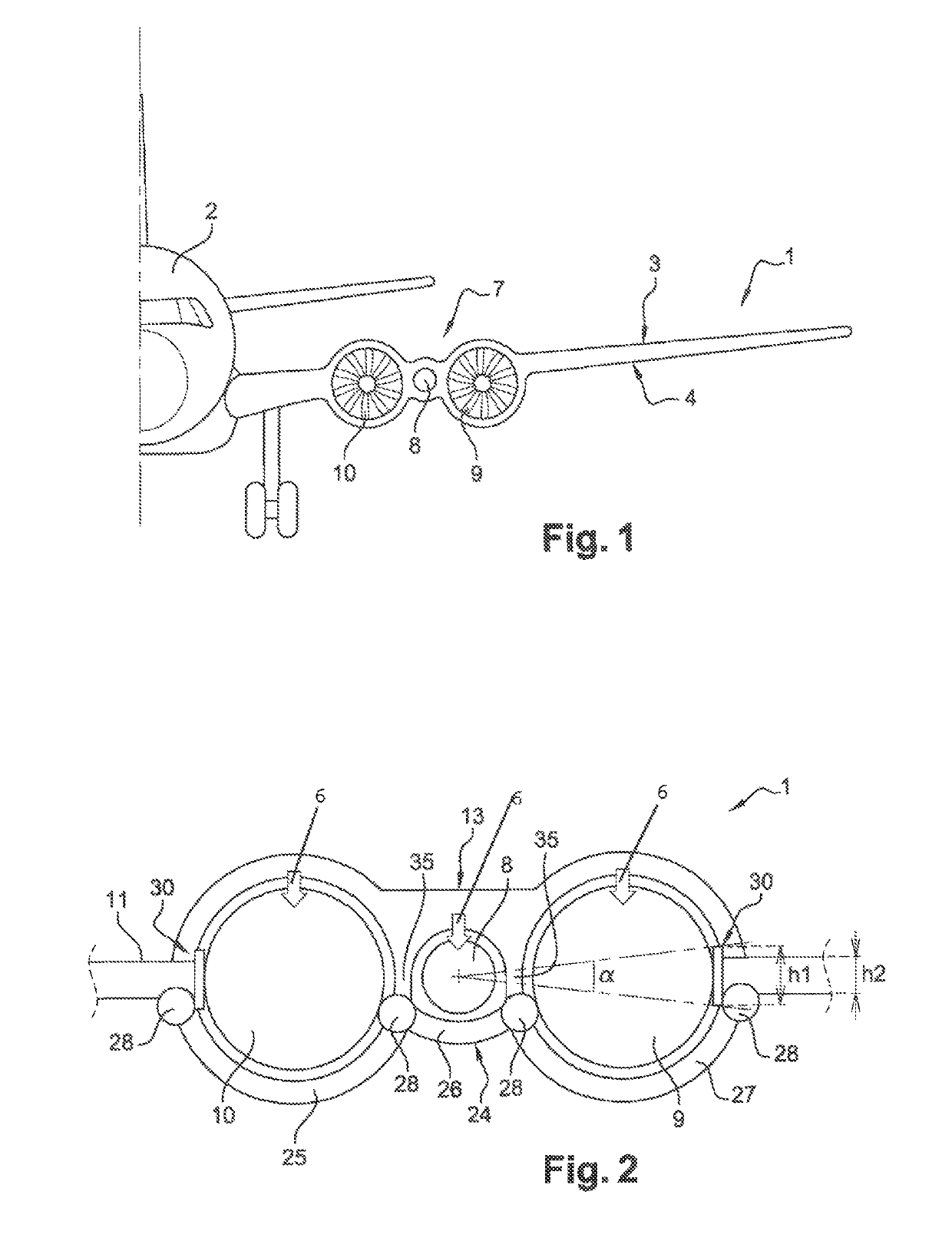
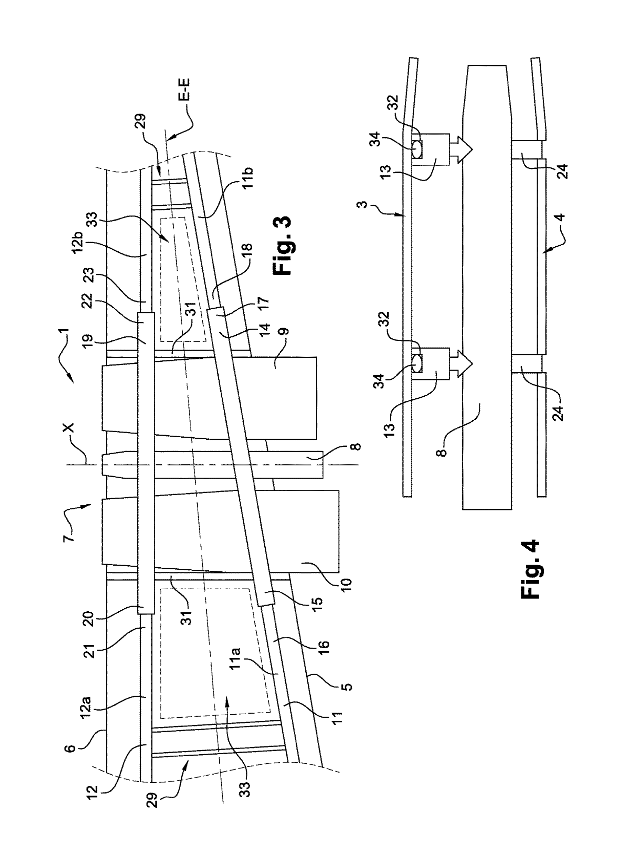
[0011]This object is achieved according to the invention by a propulsive wing of an aircraft having at least two structural spars, upstream and downstream, that extend in a wing span direction of the wing, and a propulsion assembly comprising at least two fans each driven by at least one gas generator, at least one gas generator extending along an axis that is remote from the axis of rotation of at least one fan, and at least one of the spars comprising a first part and a second part that are separated by the propulsion assembly in the wing span direction of the wing, the first and second parts being interconnected by a rigid structure shaped so as to extend at least in part around said fans, the gas generator and the fans each being supported directly and individually by the rigid structure.

[0012]This solution thus makes it possible to achieve the object mentioned above. In particular, the wing separated by the propulsion assembly makes it possible to reduce the impact on the drag ...


PUM


Abstract

A propulsive wing of an aircraft including at least two structural spars, upstream and downstream that extend in a wing span direction of the wing. A propulsion assembly includes at least two fans that are each driven by at least one gas generator. The at least one gas generator extends along an axis that is remote from the axis of rotation of at least one fan. At least one of the spars includes a first part and a second part between which the propulsion assembly is arranged. The first and second parts are interconnected by a rigid structure that is shaped to extend at least in part around the fans. The propulsion assembly is supported by the rigid structure.

Description

1. FIELD OF THE INVENTION[0001]The present invention concerns the field of aeronautics and relates to a propulsive wing of an aircraft, and more particularly a wing equipped with at least one propulsion assembly formed by at least one gas generator and at least two fans. The invention also relates to an aircraft equipped with a propulsive wing of this type.2. PRIOR ART[0002]The natural development of multiple-flow turbojet engines that have a fan is to reduce the specific consumption while increasing the bypass ratio, which is the ratio of the secondary flow to the primary flow. In the case of conventional twin-spool bypass engines comprising one turbine connected directly to the fan, the increases in the bypass ratio are limited in particular by the difficulty in reconciling the necessary slowing in the speed of rotation of the fan and the impact of such a slowing on the increase in load and the deterioration in the performance of the low-pressure turbine. The architectures of type...

Claims


Application Information

Patent Timeline
Patent Type & Authority Patents(United States)
IPC IPC(8): B64D27/18B64C3/32B64C3/34
CPCB64C3/34B64C3/32B64D27/18Y02T50/40
Inventor BEUTIN, BRUNO ALBERT
Owner SN DETUDE & DE CONSTR DE MOTEURS DAVIATION S N E C M A
Why Eureka
Try Eureka